
Specifications

8
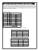
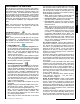
STANDBY-BATTERY CALCULATION WORKSHEET
Use the procedure given below to determine the required standby battery capacity in Ampere-Hours (AH). NOTE: It is not totally
accurate to merely divide the combined standby current (in amperes) by the battery amp-hour rating to obtain the standby time (in
hours), since other factors (control-panel charging capabilities, temperature, battery condition, battery discharge rate, etc.) affect
battery operation. The following calculations will yield the theoretical standby time of the 4AH and 7AH batteries at room tempera-
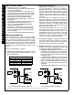
ture. NOTE: JP3 is used to provide standby power to D1 and D2 power output terminals. When AC power is removed, these ter-
minals will not have battery standby voltage available. UL has only evaluated the system with JP3 removed. In addition, this
Standby-Battery Chart has not been evaluated by UL.
1. STANDBY CURRENT
STANDBY CURRENT (Amps)
DEVICE QTY EACH TOTAL
GEM-ACM1D 1 X 0.04 = 0.04
GEM-2D 1 X =
Reader 2 of 2 X =
Door Strike 1* X =
Door Strike 2* X =
X =
X =
X
=
TOTAL STANDBY CURRENT
Amps
Reader 1 of 2 X =
*Not applicable if JP3 is not installed. JP3 must NOT be installed in UL installations.
Current Capacity (AH) Standby Time
0.35A 7.0 AH 20 Hours
0.70A 6.3 AH 9 Hours
1.4A 5.6 AH 4 Hours
1.8A 5.13 AH 2.85 Hours*
7AH Battery Standby Time @ 20 degrees C
Current Capacity (AH) Standby Time
0.2A 4.0 AH 20 Hours
0.40A 3.6 AH 9 Hours
0.80A 3.2 AH 4 Hours
1.40A 2.8 AH 2 Hours
1.8A 2.61AH 1.45 Hours*
4AH Battery Standby Time @ 20 degrees C