
Specifications

6
the door contact is restored.
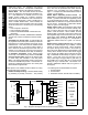
6. Other Connections and Jumpers
Card Reader Power Jumper (JP1). Determine the
power requirements of the card reader in use and con-
nect jumper JP1 as follows: If a 12V device, place the
jumper on the top two pins (pins 1 and 2) and if a 5V
device, place jumper on the middle and bottom pins
(pins 2 and 3). Note: Jumper set to 12V from factory.
See wiring diagram for details.
Keypad Address Jumper (JP2)
. Notice that JP2 has
5 pairs of pins, each pair forming a vertical "column".
For JP2, the Access reader uses a keypad location in
the system for communication (Keypad #1 must NOT
be selected as an ACM type). The JP2 pin "columns"
1-4 must reflect (in hexadecimal) the keypad/ACM ad-
dress to be selected in the panel programming. There-
fore, if keypad address 2 is to be used for the ACM in
panel programming, the shunt connector should be
placed on the second "column" of pins marked "2" in
JP2. If keypad address 3 is to be used, place jumpers
on the first and second "column" of pins marked "1" and
"2". See Fig. 3 and Table 4 below for jumper place-
ment. Note: Panel programming is to be performed
later, in the section below "Panel Programming". Pins
marked "5" are used for the high security "Degrade
Mode Off Jumper", see next section below.
High Security--Degrade Mode Off Jumper (JP2 Pins
#5). This pair of pins on the far right (5th "column") de-
termines the operation of the GEM-ACM1D module
when a bad checksum computation is encountered.
From the factory, JP2's fifth "column" of pins are un-
populated, and therefore provides a lower security level
for the system as follows:
•
When the GEM-ACM1D detects a bad configuration
data checksum computation and loses communica-
tion with the panel (unable to receive an update), the
GEM-ACM1D will grant access to any user who has
a SIA 26-bit Standard card or a NAPCO proprietary
36-bit card.
If higher security is desired, fifth "column" of pins in JP2
can be shorted using shunt provided and the GEM-
ACM1D will not allow access.
Door Lock Power - Battery Backup Jumper
. Placing
a shunt connector on jumper JP3 (factory default) en-
ables battery power backup for the D1 PWR and D2
PWR outputs. Jumper JP3 will not affect the battery
standby operation of all other terminals on the GEM-
ACM1D. Therefore if AC power is lost, the GEM-
ACM1D will continue to function, but doors will not be
powered unless powered by a separate circuit. When
this jumper is not installed, the GEM-ACM1D fulfills the
UL 4 Hour Standby requirement (and is allowed to re-
main a UL listed mercantile burglary accessory to the
GEM-X255) even when drawing the maximum rated
current (1.5A) from the door locking mechanism power,
with the 4 amp-hour battery connected. If jumper is in-
stalled and AC is lost, doors will be powered by the bat-
tery, but batteries may be discharged quickly if the door
locking mechanism requires power to operate. See the
Standby Battery Calculation Worksheet on page 8.
SECOND DOOR INSTALLATIONS
The GEM-2D is a module that connects to the GEM-
ACM1D. It allows the GEM-ACM1D to independently con-
trol a second access relay using a separate card reader.
The GEM-2D is basically identical to the GEM-ACM1D,
except that the GEM-2D uses separately wired card read-
ers, door contacts and locking device relays that all func-
tion in the same manner as the GEM-ACM1D. In addition,
readers connected to the GEM-2D do not provide Arm/
Disarm capability. See "Typical Installations", Options 1
and 2 on page 2.
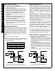
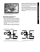
Installing the GEM-2D
When connecting the GEM-2D to the GEM-ACM1D, insert
the pins of the GEM-2D into receptacles J4F and J5F lo-
cated on top of the GEM-ACM1D. Before inserting, align
all pins and receptacle sockets, then fully insert the GEM-
2D into the GEM-ACM1D. See Fig. 4 below illustrating the
installation of the GEM-2D into the GEM-ACM1D.
JP1
JP2
5V
12V
Card Reader
Power Jumper
Keypad
Jumper
(1-4)
1 2 3 4 5
High Security
Jumper
(5)
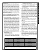
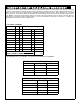
Fig. 3: Jumpers JP1 and JP2
JP2
: Pins "columns" 1 through 5 are depicted from
left to right using the illustrations in the table below:
Unconnected jumpers are white:
Shorted Jumpers are black:
Keypad
Address
JP2 Jumper Pin
"Column" Shorted
JP2
Illustration
1 Not used, must be a keypad.
Do not configure ACM for Keypad #1
2 2
3 1 and 2
4 3
5 1 and 3
6 2 and 3
7 1 and 2 and 3
8 4
9 1 and 4
10 2 and 4
11 1 and 2 and 4
12 3 and 4
13 1 and 3 and 4
14 2 and 3 and 4
15 1 and 2 and 3 and 4
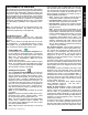
Table 4 Keypad Jumper JP2 Configuration
SECOND DOOR INSTALLATIONS