
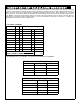
Specifications

2
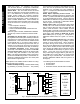
GEM-ACM1D Power Supply
The GEM-ACM1D has an integral power supply which in-
cludes two primary linear regulators. The first regulator is
used to power the panel, the card readers and to re-charge
the battery. The panel and card readers are supported
with battery standby. The second regulator is used to sup-
ply up to 1.5A 12VDC for the door locks, which provides
enough current to support two 750mA magnetic locks.
The Door Lock Power has an option to enable battery
standby with a shunt connector placed across jumper JP3
(factory default). The battery is prevented from damage
caused during extended power failures with a battery drop
out circuit that disconnects the battery when there is no AC
present and battery voltage drops to approximately 9VDC.
When AC is restored, the battery is automatically re-
connected and begins to recharge.
The GEM-ACM1D tests the battery under load every 4
hours and when the RESET button is pressed. The low
battery condition will only restore after it passes the active
test. The duration of this test is 15 seconds.
There are several advantages to this power supply design.
The separation of the door lock power from the rest of the
system reduces the likelihood that turning off the power to
the door lock coils will affect performance of the system.
The use of linear versus switching regulators significantly
reduces electrical noise that may hinder the sensitivity of
proximity card readers.
LIST OF ACCESSORIES
HID Prox Point Plus Model 6005B
Any UL 294 Listed door lock
Proximity cards: Two card formats are supported:
(1) NAPCO standard 36 bit format or
(2) HID standard 26 bit format.
SYSTEM REQUIREMENTS
The following system hardware is required:
Gemini GEM-X255 Control Panel version 5 or higher.
EPROM Upgrade must be installed in control panel.
PLAN YOUR INSTALLATION
Before installing your GEM-ACM1D access control acces-
sory, give careful consideration to the design and physical
layout of the system. Access control points, keypad
zones, ACM zones and all other system components
should be planned in advance to ensure an efficient and
complete installation. It is recommended that you perform
all installation steps in the same sequence as is listed in
this manual.
After selecting all access locations, be sure to then locate
the GEM-ACM1D as closely as possible to the selected
access control doors, easily accessible for servicing, and
within 1000 feet of the GEM-X255 control panel. Standard
22-24 gauge wire is recommended for all connections be-
tween the panel and the GEM-ACM1D, and 18 gauge wire
for all door strikes. Avoid running wires parallel to other
types of wiring that can cause electrical interference.
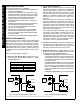
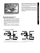
Typical Installations
There are two basic ways the GEM-ACM1D may be in-
stalled to provide access control, both are described be-
low:
Option 1 uses a single card reader on the exterior of the
restricted area and a "Request to Exit" button within the
restricted area. This method only requires a single card
reader for each access door. This method is limited in
that only entrance via the card reader is logged or
printed
§
. The use of the "Request to Exit" button is not
logged (anyone can exit).
Option 2 uses 2 card readers (one reader mounted in-
side and another outside the restricted area); both con-
nected in parallel to a single card reader interface. This
method requires presenting the credential for both entry
and exit from the restricted area. Although each presen-
tation of the credential is logged and printed
†
, whether
the presentation was used to enter or exit the restricted
area cannot be determined.
Integrating the Fire Alarm System
Before installing the access control system, be sure to con-
sult with the authority having jurisdiction to be sure to com-
ply with all local codes. NFPA requires that the Fire Alarm
System has some control over the access doors. In the
event of a Fire Alarm or the loss of primary power (typically
AC), all access doors must be unlocked.
The "Emergency Free Access" zone is designed for this
integration. The output(s) from the fire alarm system must
be wired so that if there is a fire alarm or AC failure of the
fire alarm system, the "Emergency Free Access Zone" is
either shorted or opened. See page 3 for recommended
programming and wiring information.
Keypad Placement
A keypad should be located near any access door that can
be used to arm the system, so that the status of all the
zones up to the door can be determined (UL grade A re-
quirement).
Additional Accessory Requirements
Up to three GEM-X255 zones may be dedicated to each
Access door. These three zones are the (1) Door, (2)
Forced Entry Zone and (3) Door Ajar Zone. If used, each
of these zones (up to 24 on a full system) will require either
1 of the 8 panel hardwire zones, a GEM-EZM8 zone or a
Wireless zone. If the zone is not 1 of the 8 panel zones,
then either (a) the zone will require the correctly addressed
GEM-EZM8 to be physically wired to the system, or (b) a
wireless receiver (GEM-RECVX 8/16/96/255) must be
physically wired to the system.
§
A GEM-PRINT is required on the system to print.
†
A second GEM-ACM1D could also be used.