
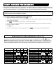
Specifications


13
By default all users (i.e. their proximity cards) are active;
the schedules restrict user card access. For example, if
an employee works 9AM through 5PM, program the
schedule to turn off starting at 5PM for the next 16
hours (until 9AM the next day). This schedule can also
be programmed as follows: Set user to be "Initially
Off" (see step 3 "User Options" above), then schedule
to turn on at 9AM for the next 8 hours.
To create an access schedule, click the Schedule As-
signment button and select the Schedule tab. For the
first user, enter as follows:
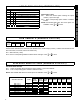
Description: Enter text in the Description column
(such as the name of the user).
Event: Enter a description of the event in the Event
column (such as "User off" to restrict access during a
period of time). The following is a partial list of events
for the GEM-X255 panel associated with access con-
trol:
• External Relay On (RB3000)
•
User On (Enable)
• User Off (Disable)
Index
: The Index column is used to associate an event
to another "object" configured elsewhere in the system.
In access control systems, the object typically is a spe-
cific user/access card number or a specific External Re-
lay number.
Normal Time: Since users are always enabled unless
restricted, the Normal Time will reflect the (a) the time
the period of restriction begins and (b) the length of time
the period of restriction will remain in effect. For exam-
ple, if you wish to allow a user access only between
their working hours of 9AM through 5PM, enter (a) the
time of day (in 24-hour military time) the period of re-
striction will begin (enter "17:00"), and (b) the length of
time, in hours, this period of restriction will remain in ef-
fect (enter 16 hours). Therefore the entry will be:
"17:00-16:00".
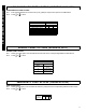
Holiday Time
: Used to restrict a recurring block of
time. For example, if you wish to restrict access every
year during the "Thanksgiving" holiday (which always
occurs on the 4th Thursday of November), enter as fol-
lows: (a) Click the Holiday Dates tab; (b) Type in a de-
scription of the holiday and click in the Date column to
open the Holiday Scheduler window. In the Date field,
all that is needed is November, therefore enter "11/**/
***" (*=wildcard). In the Day-of-Week field, enter "Th",
and in the Week Number field, enter "4" to designate
the 4th week. Press OK to save the data and press
Apply
to save the holiday. (c) Program a time span for
all scheduled holidays: Select the Schedule tab, click in
the Holiday Time column of the schedule you are
changing (the "Time Schedules" window opens). Click
to highlight a blank time schedule and click
Edit
. In the
Time Scheduler dialog, enter "0:01" in the Start Time
field to signify 12:01AM, and enter 24 in the Time
Length Field. Press OK three times to save all data.
Scheduled restricted time can overlap with other sched-
uled restricted time if needed.
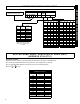
Date: Enter the dates of the week you wish to include
with the previously programmed "Normal Time". For
example, the user who works 9AM-5PM, Monday
through Friday, click in the Date column of the schedule
you are changing (the Date Schedules window opens).
Click Day of Week drop down box and click to highlight
the days you wish to include.
IMPORTANT:
After adding, changing or removing a
scheduled event, you must restart the control panel to
ensure that all new or existing scheduled events will
occur properly and without delay. To restart the panel
locally:
Remove jumper JP5 from the top two pins
("Normal") and place the jumper on the bottom two pins
("Config"); then replace the jumper on the top two pins.
To restart the panel remotely via PCD-Windows*:
Click the
Status/Control
button and click
Restart
Panel. Note that the remote connection to the panel
will be lost.
7.
Download to Control Panel
Before proceeding, save your work (File, Save Work).
Press the Panel Communication button. In the Select
Transfer Operation
drop-down box, select Download
to Panel. Check
User Program Area
,
Dealer Pro-
gram Area and Description Area. Click OK to initiate
the data transfer to the control panel. In UL installa-
tions, you must disable remote downloading (no unat-
tended downloading allowed) and after changing the
program, you must verify panel operation at the panel
site.
APPLYING POWER
Before applying power, it is recommended to first
download the panel program using PCD-Windows
Quickloader download software. See the section
"Programming the GEM-ACM1D" on page 9. Once the
program is downloaded, applying power to the system
will initiate communication from the control panel to the
GEM-ACM1D. When communication is complete,
cards can then be programmed, tested and distributed
to users.
After downloading the panel program, first apply power
to the control panel by first inserting the transformer into
a standard 120V household duplex receptacle, then
connect the flying battery leads. System troubles will
appear at the keypad (due to the lack of ACM power, a
keypad/ACM trouble will appear). The zones associ-
ated with the doors will be open, and press <RESET>
to silence/acknowledge the Keypad/ACM trouble.
Next, apply power to the GEM-ACM1D (and GEM-2D if
installed) by inserting the transformer into a standard
non-switched 120V duplex receptacle, securing the
transformer via the center duplex receptacle screw.
Connect the flying battery leads to battery. There are
three LEDs on the face of the GEM-ACM1D module
which will light as follows: When power is applied, the
green AC ON LED on the module will turn on (steady).
Within the first 30 seconds of applying power to the
GEM-ACM1D / GEM-2D modules, the red polling LED
will flash rapidly (indicating it is uploading the panel pro-
gram). After a few seconds, this red polling LED will
PROGRAMMING
* For local programming or downloading only.