
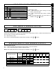
Specifications


12
The output(s) from the fire alarm system must be wired
so that if there is a fire alarm or AC failure of the fire
alarm system, the "Emergency Free Access Zone" is
either shorted or opened. See Figure 7 for recom-
mended wiring.
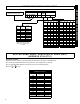
Wiring the Fire Panel to the Emergency Free Ac-
cess Zone:
a. Wire a 2.2K EOLR across the Common and N/O
terminals of the dry fire panel alarm relay.
b. Wire "Emergency Free Access" zone (-) to Common
of Fire panel dry AC ON relay.
c. Wire Fire panel AC ON relay N/C to Common of fire
panel alarm relay.
d. Wire Fire panel alarm relay N/O to "Emergency Free
Access" zone (+).
3.
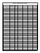
Create an ACM User & Enter User Codes
Click the User Assignment button, and select the User
Assignment tab. Configure a user (1-255) by entering
or selecting information in the areas provided:
Description
: Enter a description of the user, such as
their name.
Code: Enter the code of the proximity card assigned to
that user. Enter all numbers embossed on the card it-
self, and if there is a Facility Code, use the least signifi-
cant digit as the first number of the Code. For example,
if the embossed card number is 78799 and the Facility
Code is 12, enter 278799 in the Code column for the
user selected.
AL (Authority Level): Select an Access Level (assigned
to the proximity card) from the drop down list. 0=No
Access, 1=Disarmed Access, 2=Always Access. For
example, if you wish to give the user assigned to this
card the ability to enter the premises while armed (and
then disarm via a keypad inside the premises), select
level "2". This selection corresponds to address 0013
in Direct Address Program Mode where bits 01 and 1
are used (00= No Access, 01= Disarmed Access, 10=
Always).
Code Type
: Determines the category assigned to the
code (and thus to the specific proximity card). The
types include "No Arming", "Arm/Disarm", "Arm Only".
This selection corresponds to address 0013 in Direct
Address Program Mode where bits 2 and 3 are used
(00= No Arming, 01= Arm/Disarm, 10= Arm Only).
User Options: The IO ("Initially Off") column indicates
whether the user is initially "On" or "Off". For example,
if a user is "Off", then this user will always be disabled
unless there is a "User On" schedule programmed to
enable him (see step 6 "Create an ACM Schedule" be-
low). The default state for each user is
"On" (unchecked). If a user has a "User On" event
schedule, that the state for the user be "Off" (checked).
The remaining options are not used for ACM Program-
ming, and will be grayed-out when a valid ACM area is
selected in the "ACM Area" column.
Area: The Area column and the ACM Area column are
mutually exclusive--either can be used but not both with
one user (row). The Area column assigns the keypad
user code to an area. To assign the user to an ACM
Area, see ACM Area section (below). Click the drop-
down box to display the areas, and click each area to
highlight and select.
ACM Area: Assign a user (and their assigned prox-
imity card) to an ACM area. Click the drop-down box to
display the areas, and click each area to highlight and
select. See also step 2 ACM/Keypad Assignment
("Arm All Areas Allowed") and step 5 Configure Areas
(
Area Assignment
button).
4. Edit Zones (Zone Assignment)
In section 3 above, zones were selected to possess
certain properties. For example, you may have as-
signed zone 1 to activate when the access door is
opened (wired to door contacts). You may wish to edit
each assigned zone with respect to how the system is
intended to be used.
For example, if the system is designed to allow a user
to access an armed system, then enter a disarm code
at an interior keypad, you would need to program the
zone as an Entry/Exit zone. However, if the system is
designed to be disarmed before entry, you may wish to
program the zone as a Perimeter zone. To edit zones,
proceed as follows:
Click the Zone Assignment button and the list of pro-
grammed zones appears. Double-click the zone you
wish to edit and the Zone Edit window appears. Click
to select a
Zone Label
, or double-click the Zone Label
to edit (Edit Zone Label window). A Zone Description
can be added, and Reporting Codes can be configured.
When complete, click OK to save.
5. Configure Areas (Area Assignment)
As previously explained in step 2 (Keypad Assign-
ment button, ACM Assignment tab), the Arm All Areas
Allowed
attribute is associated with the User Assign-
ment screen. In addition, Arm All Areas Allowed is
also associated with the Area Assignment screen. The
Area Assignment tabs describe how different areas
function with relation to each other. Press the
Area As-
signment button, and view the three tabs:
Area Description tab: Type in text descriptions of
areas and messages as required.
Area/Disarm tab: Select areas that when disarmed
will silence the corresponding outputs located in
the selected areas.
Area Priority tab: Not to be used with "
Arm All Ar-
eas Allowed".
See also step 3 ACM Area on page 12.
6.
Create an ACM Schedule
Note: PCD-Windows download software MUST be
used to program schedules*.
Note: When the GEM-ACM1D loses communication
with the control panel, the user access schedule will be
abandoned and any user that has been programmed in
the system will be granted access.
Users are controlled by assigning them to a schedule.
PROGRAMMING
* For local programming or downloading only.