Model WC44 ENGLISH........................................3 FRANÇAIS...................................25 ESPAÑOL.....................................49 In USA - BEST Hartford, Wisconsin In CANADA - BEST Drummondville, QC, Canada REGISTER YOUR PRODUCT ONLINE AT : www.BestRangeHoods.com/register For additional Information visit www.BestRangeHoods.
READ AND SAVE THESE INSTRUCTIONS ! INTENDED FOR DOMESTIC COOKING ONLY ! WARNING TO REDUCE THE RISK OF FIRE, ELECTRIC SHOCK, OR INJURY TO PERSONS, OBSERVE THE FOLLOWING: 1. Use this unit only in the manner intended by the manufacturer. If you have questions, contact the manufacturer at the address or telephone number listed in the warranty. 2. Before servicing or cleaning unit, switch power off at service panel and lock service panel to prevent power from being switched on accidentally.
WARNING TO REDUCE THE RISK OF INJURY TO PERSONS IN THE EVENT OF A RANGE TOP GREASE FIRE, OBSERVE THE FOLLOWING:* 1. SMOTHER FLAMES with a close-fitting lid, cookie sheet, or metal tray, then turn off the burner. BE CAREFUL TO PREVENT BURNS. If the flames do not go out immediately, EVACUATE AND CALL THE FIRE DEPARTMENT. 2. NEVER PICK UP A FLAMING PAN - You may be burned. 3. DO NOT USE WATER, including wet dishcloths or towels - violent steam explosion will result. 4. Use an extinguisher ONLY if: A.
LED LAMPS The hood is provided with LED lamps wich require no maintenance. CLEANING AND MAINTENANCE Proper maintenance of the Range Hood will assure proper performance of the unit. Motor The motor is permanently lubricated and never needs oiling. If the motor bearings make excessive or unusual noise, replace the motor with the exact service motor. The impeller should also be replaced. Grease Filter The grease filters should be cleaned frequently. Use a warm detergent solution.
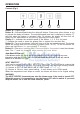
OPERATION Controls (Fig.1) A B C D R Button A = Lights on/off. Button B = Activates/Deactivates the delay-off feature. Press once (when blower is on) to activate the delay-off feature. The selected speed level that is displayed in display “C” will blink when this feature is activated. After 10 minutes, the blower will then turn off. Delay can be deactivated at any time by pressing the button again. Display C = Indicates the selected speed of the blower 1, 2, 3, or b for boost.
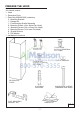
PREPARE THE HOOD Unpack hood and check contents. You should receive: 1 - Hood 1 - Decorative Flues 1 - Parts Bag (B080810993) containing: 2 - Mounting Brackets 1 - Damper Kit 1 - Flue Mounting Bracket Assembly 8 - Mounting Screws (4.8 x 38mm Pan Head) 4 - Mounting Screws (3.9 x 9.5mm Pan Head) 4 - Mounting Screws (3.9 x 6mm Flat Head) 8 - Drywall Anchors 2 - Flat Washer 1 - Installation Instructions 4 MOUNTING SCREWS (3.9x9.5mm MOUNTING BRACKETS Pan Head) 4 MOUNTING SCREWS (3.
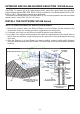
EXTERIOR AND IN-LINE BLOWER SELECTION WC44E Series CAUTION: To reduce risk of fire and electric shock, install this range hood only with Best Exterior Blower Models EB6, EB9, EB12 or EB15, and Best In-Line Blower Models ILB3, ILB6, ILB9 or ILB11. Other blowers cannot be substituited. The blower must be UL listed for Canadian and U.S. use, and evaluated for use with solid state speed control, rated 120V, 60 Hz, 6.0 A max.
IN-LINE BLOWER FIG.
INSTALL THE DUCTWORK ROOF CAP NOTE: To reduce the risk of fire, use only metal ductwork. 1. Decide where the ductwork will run between the hood and the outside (Fig.6). 2. A straight, short duct run will allow the hood to perform most efficiently. 3. Long duct runs, elbows, and transitions will reduce the performance of the hood. Use as few of them as possible. Larger ducting may be required for best performance with longer duct runs. 4. Install a roof or wall cap.
EXTERNAL BLOWER ELECTRICAL CONNECTIONS Blower connection at hood: 1. Run 2-wire plus ground power cable fromthe Exterior or In-Line Blower to the hood wiring box marked “motor connection”. (Fig.8). 2. Remove the cover from the wiring box and remove one knockout. 3. Feed 6” of cable through the knockout opening and secure the cable to the wiring box with an appropriate connector. 4. Make electrical connections at the hood.Connect white-to-white, red-to-black and greento-ground. 5.
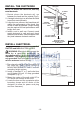
INSTALL MOUNTING BRACKETS FRAMING BEHIND WOOD CROSS SUPPORT Remove the plastic protective film from all exterior surfaces, decorative flues and filters, prior to final installation DUCTED AND NON-DUCTED HOODS 1. Construct wood wall framing that is flush with interior surface of wall studs (Fig.9). Make sure: a) the framing is centered over installation location. b) the height of the framing will allow the mounting brackets to be secured to the framing within the dimensions shown. 2.
INSTALL FLUE MOUNTING BRACKET DUCTED AND NON-DUCTED 1. Assemble the flue mounting bracket, adjusting outside width as shown. (Fig.10) 2. Carefully center the mounting bracket directly over the range hood location. 3. Secure the bracket assembly to the ceiling using (2) 4.8 x 38mm mounting screws and drywall anchors (Fig.11). Make sure the bracket is pushed into the corner, tight against the wall if necessary, and centered over the hood. Complete the installation. INSTALL THE HOOD MOUNTING SCREWS (3.
DUCTED INSTALLATION ONLY Note: Rooms with 10 or 11 foot ceiling require flue extension model AEWC345IQSB, available from your local dealer. Discard the upper flue supplied with the range hood and replace it with thw longer flue extension. 8-INCH DIA. METAL DUCT DAMPER / DUCT CONNECTOR 1. Remove protective tape from blower outlet before installing damper to hood with (4) screws supplied and tape joint with aluminum duct tape (Fig.14). 2. Run 8-inch diameter metal ductwork to the outside location. 3.
NON-DUCTED INSTALLATION ONLY Note: a. Purchase Model ANKWC345 Non-ducted Recirculation Kit from your local dealer. b. Rooms with 10 or 11 foot ceilings require flue extension model AEWC345IQSBN, available from your local dealer. Discard the upper flue supplied with the range hood and replace it with the longer flue extension. 1. Install discharge collar supplied with the range hood (Fig.17). 2. Attach the 6”-to-8” adapter to blower discharge and tape joint with aluminum duct tape (Fig.17). FIG. 17 3.
6. Temporarily secure the upper and lower flue together with duct tape as shown (Fig.21). 7. Lift the flue into position above the hood. Secure upper flue to the flue mounting bracket with (2) 3.9 x 6 mm screws (Fig.22). 8. Stretch expandable duct, attach it to the 6”-to-8” adapter and tape duct joints (Fig.23). 9. Plug power cord into wall outlet.10. Remove tape from flues and lower into position on the hood (Fig.24). FIG. 21 FIG. 22 FIG. 24 - 16 - FIG.
INSTALL FILTERS DUCTED AND NON-DUCTED HOODS NOTE: prior to use, remove protective film from the filter frame. 1. To remove the GREASE filter, pull down on latch tab to disengage the filter from the hood. Tilt the filter downward and remove (Fig.25). 2. To install the GREASE filter, align rear filter tabs with slots in the hood. Pull latch tab down. Push filter into place and release tab. Make sure the filter is securely engaged after installation. 1 2 NON-DUCTED HOODS ONLY 1.
CALIBRATE IQ BLOWER SYSTEMTM Ducted Internal Blower Hoods Only After the hood is installed and wired, engage the calibration process (our Guaranteed Performance System Technology) to ensure full-rated airflow is being delivered. Prior to calibration, ensure that all filters, light bulbs and duct system components are installed and sealed. CALIBRATION PROCESS Hold the calibration button for 3 seconds; calibration button will light up and stay on for up to 13 minutes.
WC44E Programming Mode Procedure WC44E Programming Mode Procedure The range hood is designed to work with several different blowers models. Before using the hood, the control must first be programmed to your blower model, in order to achieve proper operating speed: 1. Find the SETUP number that corresponds to the blower model that is installed with your range hood. 2. There must be power to the hood but the blower and lights must be turned off. 3.
SERVICE PARTS MODEL WC44IQ KEY NO. PART NO.
- 21 -
SERVICE PARTS MODEL WC44E KEY NO. 9 37 60 67 76 114 115 116 202 415 474 485 * AQI ARU IME PART NO. B08087958 B02300804 B02300249 B06102616 B02005322 B032904990 BE3350233 BE3334252 B03292290 B03292288 B08093413 B08016375 B080810993 B06102633 B08081849 B06145223 DESCRIPTION Grease Filters Heat Sentry Feeder Cable Wires Assembly Glass Wire Clamp Wiring Box Wiring Box Cover Wire Clamp Fairlead Led Lamp Decorative Flue Assembly Fitting Set (Includes Key No.
- 23 -