Model U102E ENGLISH......................................2 FRANÇAIS.................................15 ESPAÑOL...................................28 BEST BY BROAN, P. O.
READ AND SAVE THESE INSTRUCTIONS ! INTENDED FOR DOMESTIC COOKING ONLY ! WARNING TO REDUCE THE RISK OF FIRE, ELECTRIC SHOCK, OR INJURY TO PERSONS, OBSERVE THE FOLLOWING: 1. Use this unit only in the manner intended by the manufacturer. If you have questions, contact the manufacturer at the address or telephone number listed in the warranty. 2. Before servicing or cleaning unit, switch power off at service panel and lock service panel to prevent power from being switched on accidentally.
! WARNING TO REDUCE THE RISK OF INJURY TO PERSONS IN THE EVENT OF A RANGE TOP GREASE FIRE, OBSERVE THE FOLLOWING:* 1. SMOTHER FLAMES with a close-fitting lid, cookie sheet, or metal tray, then turn off the burner. BE CAREFUL TO PREVENT BURNS. If the flames do not go out immediately, EVACUATE AND CALL THE FIRE DEPARTMENT. 2. NEVER PICK UP A FLAMING PAN - You may be burned. 3. DO NOT USE WATER, including wet dishcloths or towels - violent steam explosion will result. 4. Use an extinguisher ONLY if: A.
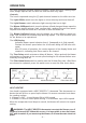
OPERATION For quiet operation and best capture of smoke, steam and other cooking impurities, always operate this unit with the slide-out visor fully open. Controls The hood is operated using the (5) push buttons located on the slide-out visor. The Light Off/On switch turns the lights on to low intensity and turns them off. The Light Dimmer switch alternates light intensity from low to high.
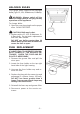
HALOGEN BULBS This range hood requires two halogen bulbs (Type JC, 12V, 20Watt max, G4 Base). WARNING: Always switch off the electrical supply before carrying out any operation on the appliance. To change bulbs: 1. Open the cover by prying from the proper slots. DO NOT ROTATE. ! CAUTION: Bulb may be hot. 2. Replace with a JC, 12V, 20 Watt max, G4 Base bulb. Do not touch replacement bulb with bare hands! DO NOT use bulbs greater than 20 Watts. Bulbs greater than 20 Watts will cause the fuse to open.
MAINTENANCE Proper maintenance of the Range Hood will assure proper performance of the unit. Grease Filters The grease filters should be cleaned when the LED Display flashes when the blower is off (i.e. 30 hours of operation). Use a warm detergent solution to clean filters. Filters are dishwasher safe. See page 12 for filter removal and installation instructions. Hood Cleaning Stainless steel is one of the easiest materials to keep clean. Occasional care will help preserve its fine appearance.
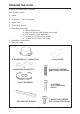
PREPARE THE HOOD Unpack hood and check contents. You should receive: 1 - Hood 1 - 8” Damper / Duct Connector 1 - Glass Visor 1 - Decorative Spacer 1 - Parts Bag containing: 2 - Mounting Brackets 4 - Machine Screws (M4 x50mm Pan Head) 4 - Flat Washers (4mm diameter) 7 - Screws (3.9 x 9.5mm Pan Head) 8 - Screws (4.8 x 12mm Pan Head) 1 - Installation Instructions 1 - Warranty Card 8” DAMPER/DUCT CONNECTOR GLASS VISOR 4 MACHINE SCREWS (M4 X 50mm PAN HEAD 2 MOUNTING BRACKETS 4 FLAT WASHERS 8 SCREWS (4.
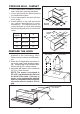
PREPARE WALL CABINET 1. Prior to wall cabinet installation, remove doors and door mounting hardware. 2. Cut an opening into the bottom panel to the dimensions shown. 3. Cut out openings for the duct and electrical wiring. 4. Install cabinet on the wall and secure per cabinet manufacturer’s recommendations. The cabinet must be securely fastened to studs and framing behind the drywall prior to hood installation.
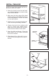
INSTALL THE HOOD NOTE: At least three people will be required to mount the hood. 1. Raise the hood up into the wall cabinet. Adjust brackets to contact inside walls of the cabinet. 2. Make sure the front edge of the hood drawer support is aligned with the front of the wall cabinet. Center the hood on the wall cabinet. 3. Tighten the (4) mounting bracket machine screws previously installed. FRONT EDGE OF CABINET FRONT EDGE OF DRAWER SUPPORT DRAWER CENTERED 4. Fasten the hood to the cabinet with (8) 4.
INSTALL THE DUCTWORK NOTE: To reduce the risk of fire, use only metal ductwork. 8” ROUND DUCT EXTERIOR BLOWER 8” TO 10” ROUND ADAPTER 1. Choose the location where the exterior blower will be mounted. See illustrations below for mounting location suggestions and restrictions. 2. A straight, short duct run will allow the hood to perform most efficiently. 3. Long duct runs, elbows and transitions will reduce the performance of the hood. Use as few of them as possible.
WIRING CAUTION: All electrical wiring should be done by a qualified person (s) in accordance with all applicable codes and standards. This range hood must be properly grounded. BLOWER CONNECTION AT HOOD EXTERIOR BLOWER Do not turn power on at service panel until all wires have been connected. Blower connection at hood: 1. Run 2-wire plus ground power cable from the exterior blower to the hood’s wiring box marked “motor connection”. BOX MARKED “MOTOR CONNECTION” 2. Remove the cover from the wiring box.
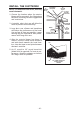
INSTALL FILTERS To install the GREASE filter, grip the latch tab and pull it down. This will disengage the filter from the hood. See Figure 16. To remove the GREASE filter, align filter tabs on the side of the filter with slots in the hood drawer. Pull latch tab down, push filter up into place and release the tab. Make sure the filter is securely engaged after assembly.
SERVICE PARTS MODEL U102E - 13 -
SERVICE PARTS MODEL U102E - Parts for stainless steel models shown. For service parts for black, white, polished brass or brushed copper models, call Broan Customer Service. KEY NO. PART NO.