
Installation instructions


9
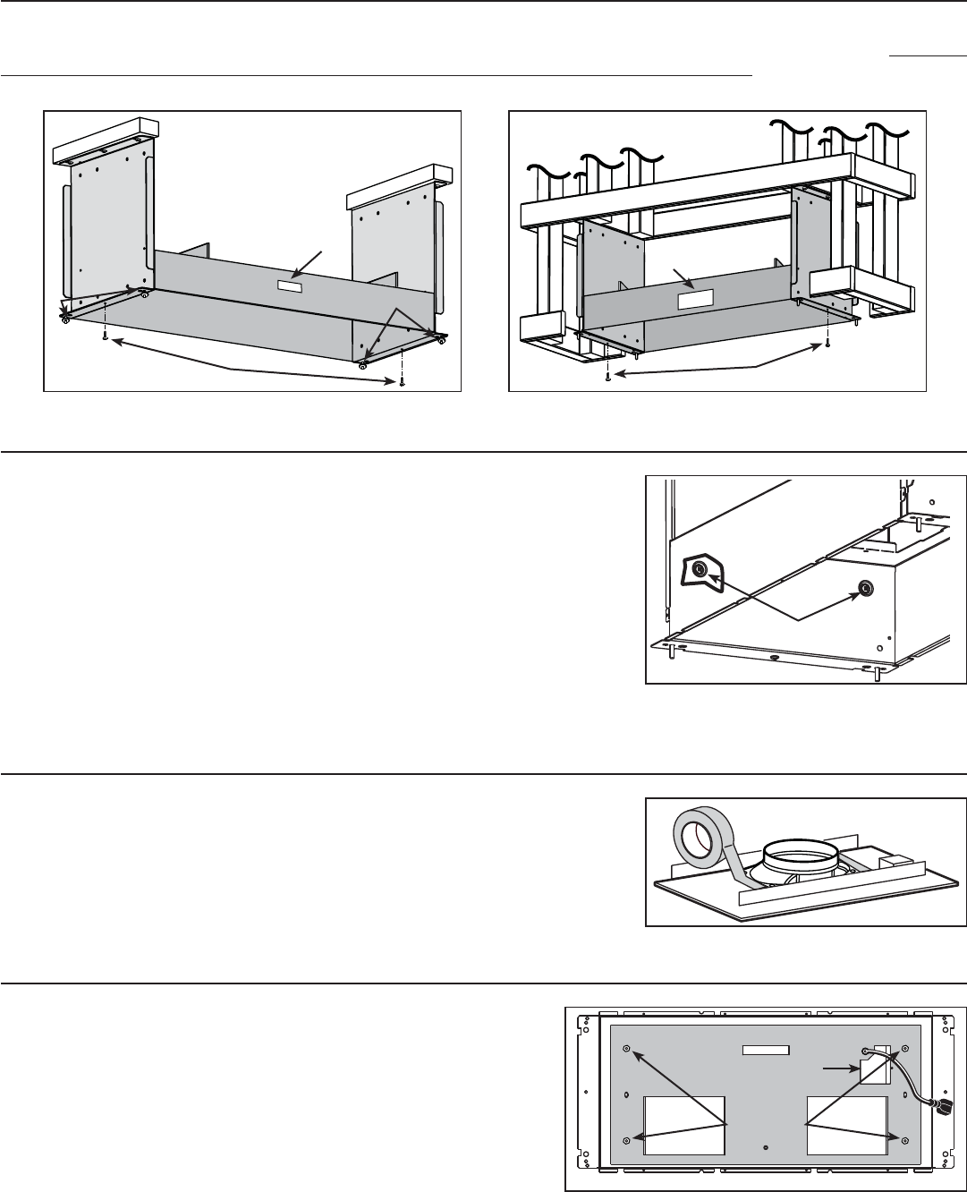
8. INSTALL BLOWER HOUSING
Use both screws (A) previously removed in step 4 to assemble the blower housing to the mounting brackets. For installation with decorative
flue cover AEIP Series only, place 4 nuts (B) (from flue cover parts bag) on the pem studs, leaving 1/4” for the hood installation. The blower
housing must be installed in such a way that its label (C) will be on the same side as the hood control side. See illustrations below.
HD0230
INSTALLATION WITH DECORATIVE FLUE COVER AEIP SERIES
HD0231
INSTALLATION WITH DRYWALL TRIM ATDIP SERIES
A
A
B
B
C
C
9. SECURE BLOWER HOUSING TO BRACKETS
From the inside, secure the blower housing to mounting brackets, using 2 no. 8 x 3/8” screws
per side.
Screws must be installed in embossed sections, see details at right.
HO0100
RETAINING SCREWS LOCATION
10. INSTALL 8” ROUND ADAPTER AND DAMPER TO ROUGH-IN PLATE
(iQ6, P3 OR P6 INTERIOR BLOWERS ONLY)
Attach transition to iQ6, P3 or P6 blower rough-in plate.
Use metal duct tape to make all joints secure and air-tight.
HO0196
11. INSTALL THE ROUGH-IN PLATE IN THE BLOWER HOUSING
Run power cable to installation location. Refer to the instructions included with
the selected blower/rough-in kit (sold separately) for details on installing the
rough-in plate. Install the rough-in plate so that the wiring box is located on the
right side when facing the hood, as specified on the blower housing label.
Connect adapter/damper or rough-in plate (according to blower model) to
ductwork. Use metal duct tape to make all joints secure and air-tight.
HD0232
WIRING COVER
LOCK NUTS