
Installation manual


Tables and Figures
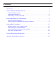
Tables
Table 1 UNITY/I Frequency, Voltage, and Bypass Switch Combinations . . . . . . . . . . . . . . . . .3
Table 2 Best Power External Bypass Switch Ratings and Applications . . . . . . . . . . . . . . . . . . .3
Table 3 UPS Dimensions . . . . . . . . . . . . . . . . . . . . . . . . . . . . . . . . . . . . . . . . . . . . . . . . . . . . .4
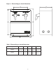
Table 4 Battery Cabinet Dimensions . . . . . . . . . . . . . . . . . . . . . . . . . . . . . . . . . . . . . . . . . . . .4
Table 5 External Bypass Switch Dimensions . . . . . . . . . . . . . . . . . . . . . . . . . . . . . . . . . . . . . .5
Table 6 Recommended Input Circuit Breaker . . . . . . . . . . . . . . . . . . . . . . . . . . . . . . . . . . . . . .8
Table 7 Maximum Permitted UPS Output Overcurrent Protection Device Rating . . . . . . . . . . .9
Table 8 Minimum Recommended Wire Sizes . . . . . . . . . . . . . . . . . . . . . . . . . . . . . . . . . . . . . .9
Table 9 Choosing an Installation Wiring Diagram . . . . . . . . . . . . . . . . . . . . . . . . . . . . . . . . .10
Table 10 Recommended Input Fuse for Models with Optional 380/400/415 VAC Input . . . . .21
Table 11 Maximum Output Current per Phase (Leg) . . . . . . . . . . . . . . . . . . . . . . . . . . . . . . . .25
Table 12 Output Voltage Reference Settings . . . . . . . . . . . . . . . . . . . . . . . . . . . . . . . . . . . . . .26
Table 13 External Bypass Switch Positions . . . . . . . . . . . . . . . . . . . . . . . . . . . . . . . . . . . . . .29
Figures
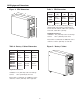
Figure 1 UPS Dimensions . . . . . . . . . . . . . . . . . . . . . . . . . . . . . . . . . . . . . . . . . . . . . . . . . . . .4
Figure 2 Battery Cabinet . . . . . . . . . . . . . . . . . . . . . . . . . . . . . . . . . . . . . . . . . . . . . . . . . . . . .4
Figure 3 External Bypass Switch Dimensions . . . . . . . . . . . . . . . . . . . . . . . . . . . . . . . . . . . . .5
Figure 4 Typical Hardwired UPS Installation . . . . . . . . . . . . . . . . . . . . . . . . . . . . . . . . . . . . . .6
Figure 5 Wiring Diagram for UT3K, UT4K, UT5K and UT8K UPS
with External Bypass Switch (L1, L2, N) . . . . . . . . . . . . . . . . . . . . . . . . . . . . . . . . . . .14
Figure 6 Wiring Diagram for UT3K, UT4K, UT5K and UT8K UPS
with External Bypass Switch and External Input Isolation Transformer . . . . . . . . . . . .16
Figure 7 Wiring Diagram for UT3K, UT4K, UT5K and UT8K UPS
with External Bypass Switch (L - N High Voltage Only) . . . . . . . . . . . . . . . . . . . . . . .18
Figure 8 Wiring Diagram for UT3K, UT4K, UT5K and UT8K UPS
with Optional 380/400/415 VAC Input . . . . . . . . . . . . . . . . . . . . . . . . . . . . . . . . . . . . .20
Figure 9 UPS Output Wiring Connections . . . . . . . . . . . . . . . . . . . . . . . . . . . . . . . . . . . . . . .22 - 24
Figure 10 Remote Emergency Power Off (EPO) Switch . . . . . . . . . . . . . . . . . . . . . . . . . . . . .28
Figure 11 Service Panel Warning Label . . . . . . . . . . . . . . . . . . . . . . . . . . . . . . . . . . . . . . . . .28