
Installation manual


27
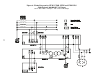
❑6. At the external bypass switch, make sure that the voltage from AC line to the bypass switch is
close to the voltage from the UPS to the loads. Use a true RMS voltmeter to measure the volt-
age between the points on the bypass switch terminal strip that are listed below.
The voltages written in the first column should be similar to the voltages written in the second
column. If the voltages are more than a few volts apart, check the connections at the ter-
minal strip and correct any wiring problems(exceptions: applications noted below, applica-
tions where UPS input and output voltages differ, such as 208 in - 240 out). If you need assis-
tance, call Best Power’s Worldwide Service or the nearest Best Power office.
AC Line Input
AC from UPS Output
• L1 - L2 11 to 12 ________ 7 to 8 ________
• N - L1 10 to 11* ________ 6 to 7* ________
• N - L2 10 to 12* ________ 6 to 8* ________
* For some installations, there is no connection at terminal 10 or terminal 6.
❑7. If you have a Break-Before-Make (BBM) bypass switch, go to step 10.
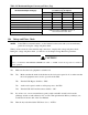
❑8. If you have a Make-Before-Break (MBB) bypass switch, make sure that the AC voltages from
the UPS output and the AC line input are in phase. Measure the AC voltage between the points
on the bypass switch terminal strip listed below.
These readings must not be more than 15 VAC. If they are, call Best Power’s Worldwide
Service or the nearest Best Power office.
• L1 - L1 7 to 11 = __________ VAC
• L2 - L2 8 to 12 = __________ VAC (some applications)
❑9. Measure the AC voltage between the following points on the bypass switch terminal strip.
This reading must not be more than 1 VAC. If it is, call Best Power’s Worldwide Service or
the nearest Best Power office.
• N - N 6 to 10 = __________ VAC (if you used wiring diagram Figure 5, 6, or 8)
• N - N 8 to 12 = __________ VAC (if you used wiring diagram Figure 7)
❑10.Once all of your readings in the voltage and phase check are acceptable, do the following:
❑a. Turn the UPS key switch to “OFF.”
❑b. Turn the UPS AC Line Disconnect Switch to “OFF.”
❑c. Turn the UPS Bypass Switch to “OFF.”
❑d. If you have one or more external battery cabinet(s), push in the main DC key switch(es).
❑e. Reattach the covers to the UPS and bypass switch.
You have finished installing the UNITY/I. Read Section 400, “Additional Requirements.” To
start the unit, see Section 100 in the
UNITY
/I User Manual.