
Installation manual


25
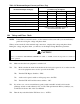
Table 11: Maximum Output Current per Phase (Leg)
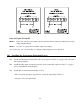
304 Voltage and Phase Check
NOTE: If the UPS has external batteries, see the instructions that came with your external battery
pack before doing the voltage and phase check.
When you have made all of the terminal strip connections, complete this voltage and phase check.
During the voltage and phase check, you will also set the Output Voltage Reference parameter.
❑ 1. Make sure that the load equipment is switched off.
❑ 2. ❑ a. Make sure that the main circuit breaker at the load service panel is off, or make sure that
the load equipment cannot receive power from the UPS.
❑ b. Turn the UPS Bypass Switch to “UPS.”
❑ c. At the service panel, switch on AC input power to the UPS.
❑ d. Turn the UPS AC Line Disconnect switch to “ON.”
❑ 3. If you have one or more external battery pack(s) with a main DC switch, hold down the
precharge switch on each cabinet for five seconds. Then pull the main DC key switch(es) out,
as indicated in Section 101 of the User Manual.
❑ 4. Turn the key switch inside the UPS front door to “AUTO.”
Maximum Output Current
per Phase (Leg) in Amperes
Nominal UPS Output Voltage(s)
UT3K UT4K UT5K UT8K
100 and/or 200 15 A 20 A 25 A 40 A
110 and/or 220 14 A 18 A 23 A 36 A
115 and/or 230 13 A 17 A 22 A 35 A
120 and/or 240 13 A 17 A 21 A 33 A
127 only 12 A 16 A 20 A 31A
208 only 14 A 19 A 24 A 38 A
120/208
Call Best Power’s Worldwide Service or
the nearest Best Power office.
127/220
CAUTION!
Before you switch the UPS BYPASS SWITCH from “UPS” to “LINE,” follow the steps below to check for
correct operation.