
Installation manual


24
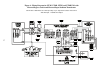
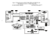
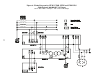
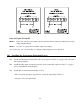
Notes for Figure 9L and 9M
NOTE 1: Connect the UPS’ green and yellow neutral-to-ground (neutral-to-earth) wire (N-G bond) to the UPS
output terminal indicated.
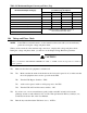
NOTE 2: See Table 11 on page 25 for maximum output current ratings.
* See Section 304, step 5, for instructions on setting the Output Voltage Reference parameter.
303 Installing the Overcurrent Protection Devices
❑1. Install the UPS input circuit breaker at the service panel. See Table 6 on page 8 and your instal-
lation wiring diagram.
❑2. Install the UPS output overcurrent protection device at the UPS output. See Table 7 on page 9
and your installation wiring diagram.
❑3. Install the load current circuit breakers or fuses.
• The load current per phase (leg) must not exceed the value listed in Table 11.
• Size per local code requirements.