
Installation manual


23
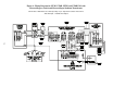
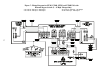
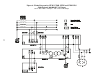
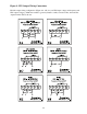
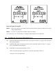
Notes for Figures 9A - 9K
NOTE 1:Connect the UPS’ green and yellow
neutral-to-ground (neutral-to-earth)
wire (N-G bond) to the UPS output
terminal indicated.
NOTE 2: See Table 11, page 25 for maximum
output current ratings.
NOTE 3: For dual-phase outputs with the
same voltage, balance the load cur-
rent between phases (legs). See
Table 11, page 25 for output current
ratings.
* See Section 304, step 5, for instructions on
setting the Output Voltage Reference parame-
ters.