
Installation manual


15
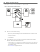
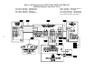
Notes for Figure 5
CAUTION!
The AC output circuit is considered as a separately-derived source. To ground this circuit, the installing electrician MUST connect the
neutral-to-ground wire (the green and yellow wire labeled WIA-0424) to the proper output terminal before making any other connections
to the UPS; for the proper output terminal connection, find your output configuration in Figure 9 on pages 22 - 24.
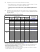
NOTE 1:See Table 6 on page 8 for the recommended input circuit breaker
size. The customer must provide overcurrent protection per National
Electrical Code (NEC) Article 240 or local code requirements.
NOTE 2:The UPS bypass switch/AC disconnect must be installed within
sight of the UPS. To properly install, complete the voltage and phase
check procedure in Section 304.
NOTE 3:The customer must provide and install this ground (earth) con-
nection per NEC Sections 250-5(d), 250-26, 250-91 and 250-92, or local
code requirements. This grounding electrode conductor must be at least
#8 AWG (8.36 mm
2
) per NEC table 250-94. If the UPS input circuit conduc-
tors are larger than #8 AWG (8.36 mm
2
), Best Power requires the ground-
ing electrode conductor to be the same size (ampacity) as the largest UPS
input circuit conductor. See NEC Section 110-3(b). Conduit is not consid-
ered an acceptable grounding electrode conductor. Best Power recom-
mends that you do notroute the grounding electrode conductor through
metallic conduit. This conductor may require protection from physical dam-
age according to local code requirements.
NOTE 4:All AC circuit conductors, including the neutral and equipment
grounding conductors, must be the same size (ampacity) and have the
same rating (75° C copper wire) and be sized according to the input pro-
tection device. The UPS input and UPS output conductors must be run
through separate conduits.
NOTE 5:The customer must provide output overcurrent protection. See
NEC Section 240-21 or local requirements. See Table 7 on page 9 for
maximum output overcurrent protection device rating and Table 11 on page
25 for maximum output current per phase (leg).
NOTE 6:See Figure 9 for proper output wiring termination and neutral-to-
ground (neutral-to-earth) connection.
NOTE 7:For maximum protection against electrical noise, use isolated
ground receptacles. See NEC Section 250-74, Exception #4, or local code
requirements.
NOTE 8:See Section 102 in this manual for installation dimensions before
installing the UPS. Use flexible metal conduit on the UPS or the external
battery cabinet if either must be moved.
NOTE 9:External UPS batteries are optional. See the information that
came with your battery pack for installation procedures.
NOTE 10:UPS output circuits shall be installed in dedicated conduit sys-
tems and not shared with other electrical circuits.
NOTE 11:The output load current must be balanced. See Table 11 on
page 25 for the maximum output current per phase (leg). The load fuse or
circuit breaker should be sized to match the load current requirements.