
Installation manual


10
❑4. Determine the correct wire size for the grounding electrode conductor.
• The grounding electrode conductor must be a minimum of #8 AWG (8.36 mm
2
) 75º C wire,
even if the circuit conductors are smaller, per NEC Table 250-94.
• If the circuit conductors are #8 AWG (8.36 mm
2
) or larger, Best Power requiresthat the
grounding electrode conductor be the same size (ampacity) as the UPS input circuit conduc-
tors.
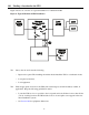
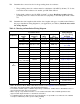
❑5. Determine the wire lengths needed and the sizes, lengths, and types of conduit needed. Refer to
the proper installation wiring diagram for your application (see Table 9). Read the notes under
the wiring diagram.
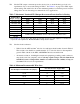
Table 9: Choosing an Installation Wiring Diagram
1
BBM = Break-Before-Make, MBB = Make-Before-Break. See the Appendix for more information.
2
380, 400 or 415 volt input requires optional internal transformer.
3
To install the 127/220 output or 120/208 output voltage combination, call Best Power’s Worldwide Service or
the nearest Best Power office for assistance.
4
With a step-up or step-down transformer. Use an isolation transformer with a 120/240 grounded center-
tapped neutral output. Donotuse a buck/boost transformer.
5
For 120/208 output, if the 208 volt loads can run at 240 volts, it is preferable to use 240 volts. The 120/240
volt output combination provides greater loading flexibility.
If you have these...
Frequency
UPS Input
Voltage
UPS Output
Voltage(s)
Output
Wires
Bypass
Type
1
..Use this Installation
Wiring Diagram
(and Output Wiring
Diagram)
220 220 L - N BBM or MBB Figure 7 (Figure 9K)
220 110/220 L1, L2, N BBM or MBB Figure 5 (Figure 9G)
240 240 L - N BBM or MBB Figure 7 (Figure 9M)
50 Hz
380, 400, or 415
2
220, 230, or 240 L - N BBM only
Figure 8 (Figure 9K,
9L, or 9M)
220 127 L1, L2, N BBMonly Figure 5 (Figure 9F)
220 127/220
3
L1, L2, N BBM only Call Best Power.
220 220 (Mexico) L1, L2, N BBM only Figure 5 (Figure 9D)
220 110/220 L1, L2, N BBM or MBB Figure 5 (Figure 9E)
220 220 L - N BBM or MBB Figure 7 (Figure 9J)
60 Hz
208 or 480
source
4
, 240 input
120/240 L1, L2, N BBM or MBB Figure 6 (Figure 9A)
200 200 L - N BBM or MBB Figure 7 (Figure 9I)
200 100/200 L1, L2, N BBM or MBB Figure 5 (Figure 9C)
208 208 L1, L2, N BBM only Figure 5 (Figure 9B)
208 120/208
3, 5
L1, L2, N BBMonly Call Best Power.
208 120/240 L1, L2, N BBMonly Figure 5 (Figure 9A)
230 230 L - N BBMor MBB Figure 7 (Figure 9L)
230 115/230 L1, L2, N BBMor MBB Figure 5 (Figure 9H)
240 208 L1, L2, N BBMonly Figure 5 (Figure 9B)
240 120/208
3, 5
L1, L2, N BBMonly Call Best Power.
50 Hz
or
60 Hz
240 120/240 L1, L2, N BBMor MBB Figure 5 (Figure 9A)