
Installation manual


9
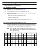
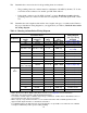
❑2. Size the UPS output overcurrent protection device (fuse or circuit breaker) per local code
requirements. Do not exceed the ratings in Table 7. See Table 11 on page 25 for UPS output
current ratings. The table below shows the maximum permitted overcurrent protection device
ratings; these are also the ratings recommended for U.S. applications.
Table 7: Maximum* Permitted UPS Output Overcurrent Protection Device Rating
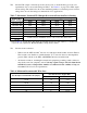
❑3. Size the circuit conductors.
• Table 8 lists the AWG and mm
2
wire size for each input circuit breaker shown in Table 6.
The conductor size shall be no smaller than the 75° C wire size based on the ampacities
given in Table 310-16 of the NEC, ANSI/NFPA 70-1993, and article 220.
• All circuit conductors, including the neutral and equipment grounding (earth) conductors,
must be the same size (ampacity) wire.Code may require a larger wire size than shown
in Table 8 because of temperature, number of conductors in the conduit, or long ser-
vice runs.Follow local code requirements.
Table 8: Minimum Recommended Wire Sizes
...use this size 75º C Copper Wire
For this input circuit breaker size (amps)...
AWG mm
2
15, 20 12 3.31
25, 30 10 5.26
35, 40, 45, 50 8 8.36
60 6 13.30
70 4 21.15
Maximum Overcurrent Protection Device Rating per Phase (Leg)
Nominal UPS
Output Voltage(s)
UT3K UT4K UT5K UT8K
100 and/or 200 20 A 25 A 35 A 50 A
110 and/or 220 20 A 25 A 30 A 45 A
115 and/or 230 20 A 25 A 30 A 45 A
120 and/or 240 20 A 25 A 30 A 45 A
127 only 15 A 20 A 25 A 40 A
208 only 20 A 25 A 30 A 50 A
127/220
120/208
Call Best Power’s Worldwide Service or the nearest Best Power office.
*Refer to Table 11 on page 25 for UPS output current ratings and size the UPS output fuse or circuit break-
er per local code requirements. Do not exceedthe ratings listed in Table 7.