UNITY/I TM UT3K, UT4K, UT5K and UT8K Single-Phase Uninterruptible Power Systems Installation Manual MLS-0351C-OL Copyright 1994-1997 Best Power. All rights reserved.
IMPORTANT SAFETY INSTRUCTIONS! SAVE THESE INSTRUCTIONS! This manual contains important instructions for your UNITY/I™ UPS. The installation and use of this product must comply with all national, federal, state, municipal, or local codes that apply. If you need help, phone Best Power’s Worldwide Service at 1-800-356-5737 (U.S.A. or Canada) or call the nearest Best Power office. Customers anywhere can call 1-608-565-2100 to reach Best Power’s Worldwide Service.
Who needs to use this installation manual? This manual contains instructions for the installation of hardwired units (units that do not have an input line cord or output receptacles). The installation and wiring instructions in this manual are for use by a qualified electrician only.
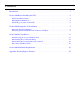
Contents Introduction . . . . . . . . . . . . . . . . . . . . . . . . . . . . . . . . . . . . . . . . . . . . . . . . . . . . . . . . . . . . . . .1 Section 100 Before Installing the UPS . . . . . . . . . . . . . . . . . . . . . . . . . . . . . . . . . . . . . .2 101 Pre-Installation Check . . . . . . . . . . . . . . . . . . . . . . . . . . . . . . . . . . . . . . . . . . . . . . . . .2 102 Equipment Dimensions . . . . . . . . . . . . . . . . . . . . . . . . . . . . . . . . . . . . . . . . . . . . . . . . .
Tables and Figures Tables Table 1 UNITY/I Frequency, Voltage, and Bypass Switch Combinations . . . . . . . . . . . . . . . . .3 Table 2 Best Power External Bypass Switch Ratings and Applications . . . . . . . . . . . . . . . . . . .3 Table 3 UPS Dimensions . . . . . . . . . . . . . . . . . . . . . . . . . . . . . . . . . . . . . . . . . . . . . . . . . . . . .4 Table 4 Battery Cabinet Dimensions . . . . . . . . . . . . . . . . . . . . . . . . . . . . . . . . . . . . . . . . . . . .
Introduction This UNITY/ITM Installation Manual is for models that do not have an input plug. A qualified electrician must install the AC wiring for these models. The end-user may wish to read this manual, especially Section 100 and the Appendix. However, a qualified electrician must install hardwired units. In the step-by-step instructions, boxes ❑ are provided so that the electrician can check off each step as it is completed.
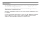
Section 100: Before Installing the UPS 101 Pre-Installation Check Find the following information. Use the labels on the equipment. UPS: • kW rating (see UPS model #): • AC volts in (range): • • AC volts out (range): Frequency: Load equipment: • Combined kW rating: • AC voltage(s): • Frequency: __________ kW ❑ 200 - 240 VAC (standard) ❑ 380 - 415 VAC (optional) 100 - 127 VAC, 200 - 240 VAC (all models) 50/60 Hz. On line, input frequency is the same as output frequency.
Table 1: UNITY/I Frequency, Voltage, and Bypass Switch Combinations Frequency UPS Input Voltage UPS Output Voltage(s) to Load Equipment External Bypass Switch Type1 50 Hz 380, 400, or 4152 220, 230, or 240 BBM only 220 127/2203 BBM only 127 BBM only 208 or 480 V source 240 V input 120 and/or 240 BBM or MBB 200 100 and/or 200 BBM or MBB 220 110 and/or 220 BBM or MBB 230 115 and/or 230 BBM or MBB 208 208 BBM only 208 120/2083, 5 BBM only 208 120 and/or 240 BBM only 240 208
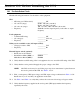
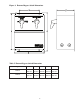
102 Equipment Dimensions Figure 1: UPS Dimensions B Table 3: UPS Dimensions C UPS Model Height (A) Width (B) Depth (C) UT3K UT4K UT5K 29 in. 737 mm 10.5 in. 267 mm 25.75 in.* 654 mm* UT8K 31.5 in. 800 mm 12.75 in. 374 mm 32.5 in.* 826 mm* *If the UPS has an external battery cabinet, add the depth of the battery connection box. For the 3K, 4K, and 5K, add 2.75 in. (70 mm); for the 8K, add 3.25 in. (83 mm). A Required Clearances: Ventilation: 4 in. (102 mm) at the rear and top.
Figure 3: External Bypass Switch Dimensions Table 5: External Bypass Switch Dimensions External Bypass Switch A B C D E BPE-02 16 in. 406 mm 8 in. 203 mm 17 in. 432 mm 12 in. 305 mm 7 in. 178 mm BPE-04 17 in. 432 mm 12 in. 305 mm 18 in. 457 mm 16 in. 406 mm 9 in.
103 Finding a Location for the UPS Figure 4 shows an overview of a typical installation for a hardwired UPS. Figure 4: Typical Hardwired UPS Installation ❑ 1. ❑ 2. Survey the site and locate the following: • Input service panel. The installing electrician should install the UPS on a dedicated circuit. • Load panel (if desired). • Load equipment. Find an appropriate location for the UPS (and external bypass switch and battery cabinet, if applicable). Keep the following guidelines in mind.
• • Provide proper UPS ventilation clearance and service clearance. • Required ventilation clearance: 4 inches (100 mm) at the rear and top. • Required service clearance: 36 inches (910 mm) at the front. • Recommended additional service clearance: 36 inches (910 mm) at each side, especially the left. Place the UPS in the proper environment. • Ambient temperature: 0° to 40° C (32° to 104° F). Battery life is longer if the temperature stays below 25° C (77° F). • Relative humidity: 0 to 95%.
Section 200: Starting the AC Installation The UPS must be installed by a qualified electrician. 201 Positioning the Equipment ❑ 1. Put the UPS in place. Follow the guidelines in Section 103. ❑ 2. If applicable, mount the external bypass switch within sight of the UPS. ❑ 3. An AC disconnect device must be located within sight of the UPS. The AC disconnect device should be one of the following: 202 • An external bypass switch with an AC disconnect switch. • A separate AC disconnect switch.
❑ 2. Size the UPS output overcurrent protection device (fuse or circuit breaker) per local code requirements. Do not exceed the ratings in Table 7. See Table 11 on page 25 for UPS output current ratings. The table below shows the maximum permitted overcurrent protection device ratings; these are also the ratings recommended for U.S. applications.
❑ 4. ❑ 5. Determine the correct wire size for the grounding electrode conductor. • The grounding electrode conductor must be a minimum of #8 AWG (8.36 mm2) 75º C wire, even if the circuit conductors are smaller, per NEC Table 250-94. • If the circuit conductors are #8 AWG (8.36 mm2) or larger, Best Power requires that the grounding electrode conductor be the same size (ampacity) as the UPS input circuit conductors. Determine the wire lengths needed and the sizes, lengths, and types of conduit needed.
Section 300: AC Installation The UPS must be installed by a qualified electrician. CAUTION! A. All UPS units contain hazardous AC and DC voltages. Because of these voltages, a qualified electrician must install the UPS and AC line service. The electrician must install AC line according to local and national codes. B. Before installing, maintaining, or servicing the UPS, always remove or shut off all sources of AC and DC power and shut off the UPS.
302 Installing the Conduit and Wiring ❑ 1. Install the conduit and conduit adapters. Refer to the proper installation wiring diagram for your application (see Table 9, page 10). Read the notes under the wiring diagram. • The AC Line Input and AC Line Output conductors must be run through separate conduits. • All UPS output circuits must be installed in dedicated conduit systems and not shared with other electrical circuits.
❑ 4. Make the UPS terminal strip connections and all other AC wiring connections. • Refer to the proper installation wiring diagram for your application (see Table 9, page 10). Read the notes below the wiring diagram carefully. • See Figure 9 for proper UPS output terminations. • Make all terminal strip connections as shown on the proper wiring diagrams. • Good grounding (earth) connections are necessary to reduce electrical noise and for safe operation of the UPS and loads.
Figure 5: Wiring Diagram for UT3K, UT4K, UT5K, and UT8K UPS with External Bypass Switch (L1, L2, N) • • • • 50 50 50 50 or or or or 60 60 60 60 Hz: Hz: Hz: Hz: 200 208 208 220 Input Input Input Input - 100/200 Output 120/240 Output 208 Output 110/220 Output • • • • • 60 60 50 50 50 Hz: 220 Input - 220 Hz: 220 Input - 127 or 60 Hz: 230 Input or 60 Hz: 240 Input or 60 Hz: 240 Input Output (Mexico) Output - 115/230 Output - 120/240 Output - 208 Output 14
CAUTION! The AC output circuit is considered as a separately-derived source. To ground this circuit, the installing electrician MUST connect the neutral-to-ground wire (the green and yellow wire labeled WIA-0424) to the proper output terminal before making any other connections to the UPS; for the proper output terminal connection, find your output configuration in Figure 9 on pages 22 - 24. Notes for Figure 5 NOTE 1: See Table 6 on page 8 for the recommended input circuit breaker size.
Figure 6: Wiring Diagram for UT3K, UT4K, UT5K, and UT8K UPS with External Bypass Switch and External Input Isolation Transformer 60 Hz: 208 or 480 VAC Source with Input Step-Up or Step-Down Isolation Transformer 240 UPS Input - 120/240 UPS Output 16
CAUTION! The AC output circuit is considered as a separately-derived source. To ground this circuit, the installing electrician MUST connect the neutral-to-ground wire (the green and yellow wire labeled WIA-0424) to the proper output terminal before making any other connections to the UPS; for the proper output terminal connection, see Figure 9 on pages 22 - 24. Notes for Figure 6 NOTE 1: See Table 6 on page 8 for the recommended input circuit breaker size.
Figure 7: Wiring Diagram for UT3K, UT4K, UT5K, and UT8K UPS with External Bypass Switch (L - N High Voltage Only) • 50 or 60 Hz: 200 Input - 200 Output • 50 or 60 Hz: 220 Input - 220 Output • 50 or 60 Hz: 230 Input - 230 Output • 50 Hz: 240 Input - 240 Output 18
CAUTION! The AC output circuit is considered as a separately-derived source. To ground this circuit, the installing electrician MUST connect the neutral-to-ground (neutral-to-earth) wire (the green and yellow wire labeled WIA-0424) to the proper output terminal before making any other connections to the UPS; for the proper output terminal connection, find your output configuration in Figure 9 on pages 22 - 24. Notes for Figure 7 NOTE 1: See Table 6 on page 8 for the recommended input circuit breaker size.
Figure 8: Wiring Diagram for UT3K, UT4K, UT5K and UT8K UPS with Optional 380/400/415 VAC Input 50 Hz: 380 or 400 or 415 Input - 220 or 230 or 240 Output 20
CAUTION! The AC output circuit is considered as a separately-derived source. To ground this circuit, the installing electrician MUST connect the neutral-to-ground (neutral-to-earth) wire (the green and yellow wire labeled WIA-0424) to the proper output terminal before making any other connections to the UPS; for the proper output terminal connection, find your output configuration in Figure 9 on pages 22 - 24. Notes for Figure 8: NOTE 1: Provide input protection per local code requirements.
Figure 9: UPS Output Wiring Connections Find the output wiring configuration (Figure 9A - 9P) for your UPS input voltage and frequency and UPS output voltage(s). Make the neutral-to-ground (neutral-to-earth) connection first, then wire the output from the UPS as shown.
Notes for Figures 9A - 9K NOTE 1: Connect the UPS’ green and yellow neutral-to-ground (neutral-to-earth) wire (N-G bond) to the UPS output terminal indicated. NOTE 2: See Table 11, page 25 for maximum output current ratings. NOTE 3: For dual-phase outputs with the same voltage, balance the load current between phases (legs). See Table 11, page 25 for output current ratings. * See Section 304, step 5, for instructions on setting the Output Voltage Reference parameters.
Notes for Figure 9L and 9M NOTE 1: Connect the UPS’ green and yellow neutral-to-ground (neutral-to-earth) wire (N-G bond) to the UPS output terminal indicated. NOTE 2: See Table 11 on page 25 for maximum output current ratings. * See Section 304, step 5, for instructions on setting the Output Voltage Reference parameter. 303 Installing the Overcurrent Protection Devices ❑ 1. Install the UPS input circuit breaker at the service panel. See Table 6 on page 8 and your installation wiring diagram. ❑ 2.
Table 11: Maximum Output Current per Phase (Leg) Maximum Output Current per Phase (Leg) in Amperes Nominal UPS Output Voltage(s) UT3K UT4K UT5K UT8K 100 and/or 200 15 A 20 A 25 A 40 A 110 and/or 220 14 A 18 A 23 A 36 A 115 and/or 230 13 A 17 A 22 A 35 A 120 and/or 240 13 A 17 A 21 A 33 A 127 only 12 A 16 A 20 A 31A 208 only 14 A 19 A 24 A 38 A 120/208 Call Best Power’s Worldwide Service or the nearest Best Power office.
❑ 5. In order for the UNITY/I to provide the desired output voltage(s), you must program the Output Voltage Reference parameter (Parameter 05). The Output Voltage Reference parameter programs the output voltage that the UPS will provide at its output terminals. To program Parameter 05, follow the steps below. a. Determine the proper Output Voltage Reference parameter setting for your application. See Table 12. Table 12: Output Voltage Reference Settings If you have wired the UPS for this output voltage..
❑ 6. At the external bypass switch, make sure that the voltage from AC line to the bypass switch is close to the voltage from the UPS to the loads. Use a true RMS voltmeter to measure the voltage between the points on the bypass switch terminal strip that are listed below. The voltages written in the first column should be similar to the voltages written in the second column.
Section 400: Additional Requirements NOTE: The remote Emergency Power Off (EPO) switch and service panel warning label described below are required to meet TÜV, per EN 50091-1 and EN 60-950. • Remote Emergency Power Off (EPO) - The EPO switch is a requirement for most 50 Hz installations (see the NOTE above). The UPS must have a remote Emergency Power Off (EPO) switch which can shut off the UPS output in an emergency, de-energizing the loads.
Appendix: External Bypass Switches If your UPS does not have output receptacles, you may have an external UPS Bypass Switch with an AC Line Disconnect Switch. Figure 3 on page 5 shows a Best Power bypass switch. The UPS Bypass Switch has three positions: Line, Off, and UPS (see Table 13). Table 13: External Bypass Switch Positions UPS Bypass Switch Position Explanation LINE Connects AC input power (line) directly to the load equipment.