
Specifications

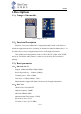


Table Of Contents

Page 4
BC204
Table 4.1 Description of pin definition
Notice: The red mark is the programming pin. When designing, it is recommended to reserve a
burning point.
5
、
Module MOQ and packaging information
Number Name definition Description
1 PB10 PB10 GPIO
2 PB09 PB09 GPIO
3 PB08 PB08 GPIO
4 PB06 PB06 GPIO
5 RX PB01 GPIO Serial burning RX
6 TX PB00 GPIO Serial burning TX
7 PA13 PA13 GPIO
8 BOOT BOOT
During serial programming, the BOOT
pin is pulled high (the programming point
is reserved)
9 PA01 PA01 GPIO
10 PA00 PA00
GPIO Wake Up Connect to external
MCU
11 PB15 PB15
GPIO RX Connect to the TX of
external MCU
12 PB13 PB13
GPIO TX Connect to the RX of
external MCU
13 PB12 PB12 GPIO
14 VDD VDD Positive electrode of module power
15 GND GND
negative electrode of module power
(3.3V)
Name MOQ(PCS) Packing
BC204 1600 tray