B.A.S.I.S.
Copyright©2014 Stanley Security, Inc. All rights reserved. Information in this document is subject to change without notice and does not represent a commitment on the part of Stanley Security Solutions, Inc. The software described in this document are furnished under a license agreement or nondisclosure agreement. This publication is intended to be an accurate description and set of instructions pertaining to its subject matter.
Contents 5 Overview 7 How B.A.S.I.S. Readers Work 10 Feature Comparisons of B.A.S.I.S. G and V 12 Setup Checklist 13 Installation and Configuration 14 Needed Components 15 Task 1: Install B.A.S.I.S. Software 15 Task 2: Install Encoder 18 Defining the system 19 Task 3: Define Card Formats 22 Task 4: Define Badge Types 26 Task 5: Define Offline Access Panels 28 Task 6: Define the Guest Locks/Readers 39 Task 7: Install B.A.S.I.S. Transport 49 Task 8: Installing B.A.S.I.S.
1 Overview This manual is your guide to B.A.S.I.S. Offline System. The information in this guide is presented in a linear manner; however, tasks to install hardware and software and configure the system for the first time do not necessarily progress in a linear manner. You will find a Setup Checklist at the end of this section to take you through the initial setup and configuration tasks in a logical sequence.
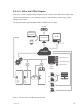
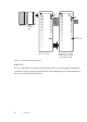
B.A.S.I.S. Online and Offline Diagram The B.A.S.I.S. system is capable of being configured as both an online and an offline access control system. This means that with B.A.S.I.S., you can manage any access control hardware, whether they are wired directly to a panel or not. This diagram describes a typical combined online and offline B.A.S.I.S. system.
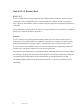
How B.A.S.I.S. Readers Work B.A.S.I.S. G B.A.S.I.S. G offline locks are designed primarily for the college/university dormitories . However, they can be effectively used in any application where a room has continuous occupancy change over a period of time, or where the lock location is remote or isolated enough that going out to reprogram the lock becomes undesirable.
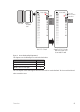
1001 issue code: 01 1001 issue code: 00 Lost card Issue codes 00 01 offset 02 of 1 03 range of 3 valid issue codes Newly encoded card Issue codes lost card 01 does not work 02 new offset 03 new 04 range Auto update B.A.S.I.S. G Lock Same B.A.S.I.S.
1001 issue code: 00 1001 issue code: 99 Lost card Issue codes 00 offset 01 of 1 02 range of 3 valid issue codes Newly encoded card Issue codes 00 01 new 02 offset 03 new range lost card does not work Auto update B.A.S.I.S. G Lock Figure 3 Same B.A.S.I.S. G Lock after use of the 1001 issue code 00 card Guest functionality diagrammed B.A.S.I.S. V B.A.S.I.S. V offline locks are designed to include all functions of B.A.S.I.S.
Feature Comparisons of B.A.S.I.S. G and V Feature Description Guest (dormitory feature) Provides the ability to issue pre-created badge IDs to students. This supports the assignment of one reader directly to the badge. Other readers may be assigned to the badge through normal access level assignment. Look ahead Issue code look ahead feature through offset and range fields. Encoding Provides the ability to encode both magstripe.
Panel password Communication password is configured at the Access Panel level. Diagnostics (PDA or Netbook/Notebook) The PDA or Netbook/Notebook will support the capability of performing diagnostics on the lock set. Cycle count/reset The lock set will maintain a current count of access grants. The count can be reset by the user. Diagnostics code This code provides some feedback of the lock set's status. Backup battery level Displays the current level of the backup battery.
Setup Checklist In the next chapter you will find complete step-by-step instructions for the first-time installation and configuration of a B.A.S.I.S. offline system. Listed below are the major steps of that process. • Task 1: Install B.A.S.I.S. Software See page 15. • Task 2: Install Encoder See page 15. • Task 3: Define Card Formats See page 19. • Task 4: Define Badge Types See page 22. • Task 5: Define Offline Access Panels See page 25. • Task 6: Define Guest Locks/Readers See page 27.
2 Installation and Configuration This chapter will guide you through performing the following tasks: Task 1 — Install B.A.S.I.S. Software Task 2 — Install Encoder Task 3 — Define Card Formats Task 4 — Define Badge Types Task 5 — Define Offline Access Panels Task 6 — Define Guest Locks/Readers Task 7 — Install B.A.S.I.S. Transport Task 8 — Install B.A.S.I.S.
Needed Components The following describes the hardware and software that it takes to create an offline B.A.S.I.S. system. Components include: • B.A.S.I.S. ET691 software, or higher • Dedicated computer or ‘workstation’ (consult your Stanley representative for complete details) • B.A.S.I.S. G or V lock(s), includes cylindrical, mortise or exit hardware trim models • Personal digital assistant (PDA) or Netbook/Notebook. See www.bestaccess.
Task 1: Install B.A.S.I.S. Software For complete B.A.S.I.S. software installation and configuration, see the B.A.S.I.S. Installation and Setup User Guide. Contact your Stanley Representative for a copy or visit www.bestaccess.com. Task 2: Install Encoder One types of encoder is available for the B.A.S.I.S. Offline system: • Magnetic Stripe encoder: Unitech Model MSR206 The card encoder or some type of encoding device (that is, an encoder or a printer with a built-in encoder) is intended for B.A.S.I.S.
Perform the following steps to set up the encoder: 1 Click Start > Programs > B.A.S.I.S. ET > System Administration. 2 At the login window, type your user name and password and then click OK. If you do not know your user name or password, see your System Administrator. 3 Click Administration > Workstations. 4 From the Workstation tab, confirm that the name of your computer is in the list. If your computer is not in the list, add your workstation by using the browse button and select your workstation.
Click to test whether the encoder is online Figure 5 Configuring the encoder 13 Click Test. Note The encoder can be tested at any time by returning to the Encoder tab. You do not need to put the encoder in modify mode to test the encoder. The corecitivity setting must be selected as "High" on the Encoding tab. 14 Click OK.
Defining the system To define a B.A.S.I.S. offline system, you need to configure: • Card Formats • Badge Types • Guest Readers • Offline Access Panels • Timezones • Access Levels • Adding a cardholder Although B.A.S.I.S. locks are offline (stand-alone) and are not managed by access control panels, you must define Access Panel settings for the locks. In effect, you define access control panels for the locks. More than one lock – called a reader in B.A.S.I.S. — can share the same panel configuration.
Task 3: Define Card Formats Defining a card format is the starting point to configure guest access control. If guest access control is not needed, a standard card format can be used or configured for a reader assignment through access levels. Badges using standard formats on compatible tracks can only be assigned readers through access levels. Perform the following steps: 1 From System Administration, click Administration > Card Formats. Figure 6 Card format 2 Click Add.
The Card Format form displays: Figure 7 Choose card format type Installation and Configuration 20
3 Choose the appropriate card format and click OK. When the guest format check box is selected, the data is offset from the start of the card by the fact that the activation and deactivation dates are encoded onto the card. Set access control track to 3. Make sure to adjust the total characters on the track to the correct access control data length. Field Length and Field Order for Facility Code, Card Number, and Issue Code is required. A 2 digit code should be used.
Task 4: Define Badge Types To use B.A.S.I.S. G offline lock basic functionality, you must define a guest badge type. This badge type allows you to define and allocate a range of badge ID numbers that will be programmed into the lock. Badge type is an ID Credential Center function used in the configuration of Guest products and determines the block or pool of badge numbers to be allocated to a group of locks. Also, badge type determines the card format to be encoded on the badge.
Figure 9 Selecting the Guest class for B.A.S.I.S. G badge type 3 Select the Guest class from the drop down box. 4 Complete all other necessary information on the tab. 5 Click the Encoding tab > Click Add 6 Select the appropriate card format to be encoded for the badge type by clicking the icon to the left of the “Guest Format”. A red arrow will appear over the card illustration > Click OK Make sure that the Guest format is selected for encoding Guest Badge Types.
7 Click the Badge ID Allocation tab and then click the ID Ranges tab. Enter the appropriate range of badge IDs for your application. Figure 11 Entering the range of Badge IDs 8 Enter the First ID number in the badge range that you want to create Note Make sure to allocate a range of badge numbers that will facilitate the future growth of a group of locks. The size of the range will determine the length of the reader list in the ‘Allow Access To’ dropdown selection on the Badge tab under Cardholders.
Task 5: Define Offline Access Panels Although B.A.S.I.S. Locks are offline (stand-alone) locks and are not managed by access control panels, you must define Virtual Access Panel settings for the locks. Using the access panel concept allows the programming of guest locks to follow the same conventions as B.A.S.I.S. online products. Up to 64 locks (called readers in B.A.S.I.S.) can share the same panel configuration.
Name the offline lock access panel appropriately for all of the possible 64 locks that it controls. The workstation name refers to the technical name of the computer to which the PDA or Netbook is attached Figure 12 Naming the offline lock access panel. 4 In the Name field, type the name of the access control panel. 5 Click OK. 6 Repeat steps 3 and 4 as necessary.
Task 6: Define the Guest Locks/Readers In the B.A.S.I.S. software, locks are referred to as readers to conform and maintain consistency with B.A.S.I.S. online terminology conventions. You can define up to 64 readers for each ‘virtual’ offline access control panel. And each reader will accept up to eight different card formats. It would be highly unusual to use this many formats in one lock. Perform the following steps: 1 From System Administration, click Access Control > Readers and Doors. 2 Click Add.
Note Selecting the ‘Offline Guest’ reader type refers to a B.A.S.I.S. G configuration. 8 Make any other selections as necessary. 9 Click OK. The Reader is listed in the Reader listing at the top of the window. 10 Repeat steps 3 – 10 for each additional lock/reader. Now that you have defined the reader operation of the lock/readers, you now need to configure the software so that the correct chassis type is assigned to the lock/reader and other offline features are configured appropriately.
Define Other Guest Reader Features 1 From System Administration, click Access Control > Readers and Doors. 2 Select the Reader that you want to define. Make sure that the check mark is next to the reader to be modified. 3 Click the Offline tab. 4 Click Modify. The Modify Offline Reader window displays. Make sure that the correct reader is selected when selecting offline features. The common door feature allows duplication of a badge range between locks.
9 In the Badge Type field, select a guest badge type from the list that was created. See page 21. 10 In the Number of badges field, enter the number of guest badges to be allocated to this reader from the total pool of badge IDs. 11 For a common door only: In the Badge Start Number field, enter the starting badge number for the subset of numbers to be used in this reader. The badge end number is automatically calculated from the numbers entered. 12 Click OK.
2 Click the Timezones tab. A list of the existing timezones will be displayed. 3 Click Add to create a new timezone to the list. Enter the timezone name Enter the time interval(s) start, end, and the days of the week when it is to be active Figure 16 Adding a timezone 4 Choose a name for the timezone and enter the choice in the Name field. 5 Choosing a name that actually represents the period of time for the timezone allows you to efficiently retrieve a timezone from a long list.
Add access levels 1 From System Administration, click Access Control > Access Levels The Access levels window displays Figure 17 Access level Installation and Configuration 32
2 Click Add to create an access level. Enter the access level name Choose readers that will be given access to Choose timezones Figure 18 Access level 3 Choose a name for the access level and enter the choice in the Name area. 4 Select the reader and the timezone configuration to be included in the access level. Remember that a selection is not made unless a checkmark is observed. 5 Click on arrow button to the right to move the reader and timezone selections to the right side of the form.
Adding a Cardholder for Standard Access Control Add a cardholder for standard access control 1 Open System Administration and go to Administration > Cardholders. A page with several tabs will be displayed. We are only concerned with the first three tabs of Cardholder, Badge, and Access Levels for common day-to-day entry. Figure 19 The cardholder general information screen 2 Click Add on the Cardholder tab. Complete all appropriate fields on the form.
3 Click the Badge tab. Choose badge type Enter badge ID if the field will accept the data Choose access doors Figure 20 The cardholder, badge information screen 4 Select the appropriate Badge Type from the drop-down list. 5 Enter a Badge ID for the corresponding badge only if the field will accept data. Sometimes a system is set to automatically generate badge ID’s and manual entry will not be required. Complete the rest of Badge tab as required by your organization.
6 Click the Access Level tab. Choose the access level for this cardholder. You may need to choose more than one access level. Figure 21 The cardholder, access level information screen 7 Select the appropriate access levels for the cardholder. Note Only the access levels accompained by a checkmark are selected for assignment. 8 Click Ok to save the record. 9 Click Encode if you are encoding badge ID’s for standard access control.
Figure 22 Question regarding the issue code 10 Click No. The Encode Badge window displays Choose the encoder. Click the Encode button to start the encoding process. Figure 23 Choosing a card format to encode 11 Make sure that the checkmark is on the card to be encoded, then click Encode. The encoder is initialized and prompts you to encode the card 12 Slowly swipe the card through the encoder as shown below.
B.A.S.I.S. G reader programming is now complete If you have finished the tasks up to this point, you have completed all steps necessary for the programming of B.A.S.I.S. G functionality or basic functionality for B.A.S.I.S. V. Please see the B.A.S.I.S. System Administration User Guide on the BEST website: www.bestaccess.com for more information on configuring time zones, holidays, access panels, cardholder management and other additional features. Task 7: Install B.A.S.I.S. Transport The B.A.S.I.S.
Figure 26 Welcome window 4 Click Next. 5 The B.A.S.I.S. communication Server service will stop as part of the installation. Deselect the box to automatically start the communication server after installation. The communications server will manually restart after SW installation has been completed.
Figure 27 Restart Communication Server Installation and Configuration 40
6 Click Next and the Select Installation Folder window will appear. Figure 28 Select Installation Folder 7 The Installation Folder will automatically install on your program file drive, unless you specify otherwise. Make sure to select “Everyone” to enable use of the BASIS Transport Tray application.”.
8 Click Next.
9 Click Next and installation will begin. Once the Installation Complete window pops up, click Close.
Initial Configuration of Transport Tray After the B.A.S.I.S. Transport Tray has successfully installed onto your workstation, you will need to set up the location of the SQL Server CE B.A.S.I.S. Transport database file that is used to store offline information. This configuration is required before installing any B.A.S.I.S. Transport software for a PDA or Netbook.
1 Select“Tools > Configure Removable Media menu item. Figure 32 Configure removable media 2 Figure 32 will show all available removable devices on the system and the following table provides the definition of each option under the ‘Configure Removable Media’ window. 3 Click the USB flash drive to highlight it. 4 Click "Configure Selected For Autodetection" button to configure the USB Flash drive. Removable Devices Definition Refresh Refreshes the list of removable devices.
5 Select Tools > Options. User can select primary transport method. Mobile Device - PDA Removable Media - USB Flash Drive Use Known Directory for Sync Database Figure 33 Options 6 Select box to sync to file on disk and check the “Automatically Detect Sync Database on Removable Media” option. This will ensure the application auto detects devices. Note You are able to select both the "Sync to Mobile Device" and "Sync to file on disk". 7 Click the “OK” button.
Known Directory If a Removable Media device is not used, a simple directory can be used that is shared on the network. It can also be a shared drive if the client and server are on the same computer. Perform the following steps. 1 Go to the B.A.S.I.S. Transport Tray home page. 2 Select Tools > Options. The following window will appear.
Task 8: Installing B.A.S.I.S. Transport for PDA The Transport PDA application is used to download information to the reader and upload history from the reader to your PDA only. There are three components to the B.A.S.I.S. Transport PDA software that needs installation: • Microsoft Mobile Device Center or Microsoft ActiveSync — program that syncs your workstation to your PDA • Microsoft.Net Compact 3.5 Framework— provides a library of necessary applications that communicates on a mobile device • Setup.
ActiveSync Installation If you are using Microsoft Windows XP, perform the following steps: 1 Connect the PDA to the B.A.S.I.S. workstation. 2 Download ActiveSync from www.microsoft.com and follow the instructions. 3 When prompted, set up a partnership with this computer and remove ALL check marks associated with programs. 4 Restart the computer after ActiveSync completely installs. 5 Test the PDA and confirm ActiveSync connectivity before proceeding. 6 Disconnect the PDA from the workstation.
PDA Software Installation Now that you have installed Activesync or Mobile Device Center, you can begin to install the B.A.S.I.S. Transport Mobile application. Note The PDA must be disconnected from the workstation prior to installing B.A.S.I.S. Transport Mobile Software. 1 Navigate to the BASIS Transport Mobile folder. Right click the setup.exe file and run as administrator Figure 35 Setup 2 Click Accept.
Figure 36 Setup wizard 3 Click Next.
Figure 37 Identify mobile device 4 Click Next.
Figure 38 Select installation folder 5 The Installation Folder will automatically install on your program file drive, unless you specify otherwise. Select "Everyone" to enable use of the Basis Transport Mobile application. 6 Click Next.
Figure 39 Confirm installation 7 Click Next.
8 The Pending Application Install window will appear four (4) times. Click OK each time. Figure 40 Pending Application Install 9 Click OK. 10 Power on and connect the PDA to your workstation. Open Windows Mobile Device Center. Figure 41 Mobile Device Center 11 Choose "Programs and Services" 12 Click More.
13 Click "Add/Remove programs". Figure 42 Add/Remove Programs 14 Only click the box for Microsoft .NET CF 3.5 and then Click OK.
Figure 44 15 Upon installation of Microsoft .NET CF 3.5, the following message will appear on your PDA: Figure 45 Restart Device 16 Click OK on the PDA and wait while the device reboots and reconnects to Windows Mobile Device Center or Activesync. 17 Once the PDA reconnects, open Windows Mobile Device or Activesync and choose "Programs and Services".
19 Click "Add/Remove Programs". Figure 46 Add/Remove Programs 20 Click the check box for each of the following: • Microsoft .NET CF 3.5 • SQL ServerCompact 3.5 Core • SQL ServerCompact3.
21 Click OK. Figure 47 Application Downloading Complete 22 Click OK and check the PDA for any prompts.
Task 8: Install B.A.S.I.S. Transport for Netbook/Notebook The B.A.S.I.S. Transport application is used to download information to the reader and upload history from the reader to your Netbook/Notebook only. There are two components to the B.A.S.I.S. Transport Client software that needs to be installed: • SQL Server 3.5 Compact — relational database for applications that run on mobile devices and desktops • Setup.exe — B.A.S.I.S. Transport Client (Netbook/Notebook) software B.A.S.I.S.
Figure 50 61 Setup Wizard Installation and Configuration
3 Click Next and the Select Installation Folder window will appear. Figure 51 Select installation folder 4 The Installation Folder will automatically install on your program file drive, unless you specify otherwise. Make sure to select “Everyone” to enable use of the BASIS Transport application.
5 Click Next.
6 Click Next Figure 53 Installation complete 7 Click Close Installation and Configuration 64
3 Set Up and Maintain Offline Locks This section describes how to use your B.A.S.I.S.® Transport software. The following topics are covered: • Transferring reader configurations from B.A.S.I.S.
Transferring Lock/Reader Configurations At this point you have successfully completed the following for the B.A.S.I.S. Offline System: • Task 1: Install B.A.S.I.S. Software See page 15. • Task 2: Install Encoder See page 15. • Task 3: Define Card Formats See page 19. • Task 4: Define Badge Types See page 22. • Task 5: Define Offline Access Panels See page 25. • Task 6: Define Guest Locks/Readers See page 27. • Task 7: Install B.A.S.I.S. Transport See page 38. • Task 8: Install B.A.S.I.S.
Transferring Lock/Reader Configurations to the PDA To transfer lock/reader configuration made through the B.A.S.I.S. System Administration on your workstation to your PDA, perform the following steps: 1 Connect your PDA to your workstation through a USB Port. Note If using a PDA, make sure B.A.S.I.S. Transport is not running. 2 Make sure that a connection has been made between Mobile Device Center and your PDA. Note To download Mobile Device Center, please see www.microsoft.
Opening Configurations on the PDA After connecting the PDA to the lock, you must open the Mobile Transport Application on the PDA to transfer all of your configurations. Perform the following steps: 1 On the PDA, tap Start > Programs > BA_TransportMobile: Figure 55 BA_TransportMobile 2 On the Transport Mobile home page, tap Menu > Open Figure 56 Open...
Figure 57 Open folder 3 Tap the BasisOfflineSeries.sdf file and the screen should refresh to reflect your selection.
Setting the Max Baud Rate: 1 Set the Max Baud Rate to 38400 by tapping the Options button at the bottom of the screen. Figure 59 Max Baud Rate 2 Once you have selected the correct sync path to your sdf file and configured the Max Baud Rate to 38400, Click OK. Configure Lockset Perform the following steps to configure your lock: 1 While the Transport tab is selected, tap the lock/reader to be programmed. Figure 60 Reader selected 2 Tap Menu and tap Configure Lockset...
Figure 61 Menu Note The password for a lock is the password programmed in the virtual access control panel. You must enter the password exactly as it was entered in the Password field on the Offline lock tab in the Access Panels screen. Capitalization must be the same. If this is the initial time the lock is being programmed or if the lock was reset to its factory default setting, leave the password field blank and tap OK.
4 If you have a Dual Validation Lock (with keypad) and you wish to preserve pins at the reader during the configuration, select the “Preserve User PINs”. Or, to reprogram the lock with the PINs stored in B.A.S.I.S., remove the check from the Preserve user pins check box. Warning: If users have reprogrammed their PINs at the lock and you do not preserve the user PINs, users will no longer be able to access the lock. The ability to program PIN’s is only available when using Card and PIN mode.
8 The Transport screen will show that it is currently downloading. Once the download is successful, the following screen will appear: Figure 64 Configuration data transfer successful Get History Perform the following steps to retrieve history events from the lock: 1 While the Transport tab is selected, tap the lock/reader history to be retrieved.
2 Tap Menu and tap Get HIstory... Figure 66 Menu Note The password for a lock is the password programmed in the virtual access control panel. You must enter the password exactly as it was entered in the Password field on the Offline lock tab in the Access Panels screen. Capitalization must be the same. If this is the initial time the lock is being programmed or if the lock was reset to its factory default setting, leave the password field blank and tap OK. 3 Enter password and Click OK.
4 The following screen should appear: Figure 68 Swipe card 5 Swipe a magnetic stripe card or proximity card through the reader. This will wake the lock to start the connection. 6 The Transport screen will show that it is currently downloading. Once the download is successful, the following screen will appear: Figure 69 History date transfer successful Diagnostics The Diagnostics option on your PDA allows you to view information about the reader and configure options for your lock/reader.
Note: Some of the diagnostic options are only available if the B.A.S.I.S. G or V lock is using a UVC board. If you are using a legacy B.A.S.I.S. G or V lock, unsupported options will be grayed out. Connect To connect to a reader using Transport, perform the following steps: 1 From the home page of B.A.S.I.S. Transport Mobile, tap on the Diagnostics tab. Tap menu and the following choices will pop up: Figure 70 Connect... 2 Tap Connect... Figure 71 Login 3 Enter your password.
Note The password for a lock is the password programmed in the virtual access control panel. You must enter the password exactly as it was entered in the Password field on the Offline lock tab in the Access Panels screen. Capitalization must be the same. If this is the initial time the lock is being programmed or if the lock was reset to its factory default setting, leave the password field blank and tap OK. Figure 72 Please swipe card 4 Swipe a magnetic stripe card or proximity card through the reader.
The table below gives a definition for all of the fields in the Diagnostics window: This Field... Shows... Firmware ID ID indicating the type of firmware in the lock. Technical support personnel may ask you to provide this information. Version Version number of the lock’s firmware. Technical support personnel may ask you to provide this information.
Disconnect Note The following diagnostic functions are performed while the PDA is already connected to the lock and the Diagnostics tab is selected. 1 To Disconnect, tap Menu and then tap disconnect. Set You have three options under the Set menu: • Date/Time/DST enable • Reader Technology • Online Mode Set: Date/Time/DST Enable Warning This feature should only be used to set time on controllers in a time zone that observes Daylight Savings.
Figure 75 Set Date/Time? 2 Click OK. Set: Reader Technology To set which reader technology the lock/reader is using, perform the following steps: 1 Tap Menu > Set Figure 76 Set Reader Tech 2 Tap Reader Tech.
Figure 77 Set Reader Tech 3 Select your reader technology.
Set: Online Mode A B.A.S.I.S. offline lock mode of operation is determined by its programming. The diagnostics information for the lock indicates the locks current Online Mode setting. For example, during an emergency you might set a lock’s online mode to Unlocked so that emergency personnel can access the room. When the event is over, you must return the lock to its original online mode setting to resume normal operation. The online mode will change only after disconnecting from the lock.
To override the current online mode of the reader, perform the following steps: 1 Tap Menu > Set > Online Mode.
Reset You have two options under the Set menu: • Diagnostics Code • Use Count Reset: Diagnostics Code Diagnostic codes are used to help identify issues with the lock, such as low battery alarms that might have occurred since the diagnostics code was last cleared. To reset diagnostic codes, perform the following steps: 1 Tap Menu > Reset > Diagnostics Code. Figure 79 Diagnostics Code Figure 80 Reset Diagnostics Code? 2 Click OK and the code will be reset to 0x0000.
Reset: Use Count Every B.A.S.I.S. offline reader counts the number of times access has been granted to a card or pin since the use count was last reset. You can use this count to track how often a lock is accessed over time. To reset the Use Count, perform the following steps: 1 Tap Menu > Reset > Diagnostics Code. Figure 81 Diagnostics Code Figure 82 Reset Use Count? 2 Click OK and the count will be reset to 0.
Unlock Once You can use the PDA to unlock a door for the locks/readers unlock duration. This feature is useful when you need to access the inside of the door to replace the lock’s batteries or perform other maintenance for the lock. Perform the following steps: 1 Tap Menu > Unlock Once. Figure 83 Unlock Once 2 Click OK if you wish to unlock momentarily. Deep Reset To reset the lock/reader to factory settings, perform the following steps: 1 Tap Menu > Deep Reset Figure 84 Deep Reset.
Download Firmware To download firmware updates to the lock from your PDA, perform the following steps: Note A firmware download is only available if the lock is fitted with the UVC board. 1 Tap Menu > Download Firmware. Note Firmware files are available by contacting Stanley Security Technical Support at (800) 392-5209. Figure 85 Download Firmware 2 Click on to browse for your firmware hex file and Click OK to download firmware.
Transferring Lock/Reader Configurations to the Netbook/Notebook To transfer lock/reader configuration made through the B.A.S.I.S. System Administration to your Netbook/ Notebook, perform the following steps: Note The following presumes the user has successfully logged into Basis System Administration and the communication server is running. It is also presumed the USB to serial cable is connected and configured on the Netbook per the manufacturers instructions.
3 Click OK. Figure 87 Full System Download 4 Upon Sync successfully completed, eject and disconnect the USB flash drive from your workstation. 5 Connect the USB flash drive to the USB/com port on your Netbook/Notebook and connect the USB to serial cable. Figure 88 Transfer Completed 6 Open the Basis Transport application.
Opening a Panel/Reader Configuration on a Netbook After saving the BasisOfflineSeries.sdf file on your Netbook/Notebook from your USB flash drive, you’ll need to upload all of your B.A.S.I.S. System Administration configurations to Transport Client. Perform the following steps: 1 Go to the B.A.S.I.S. Transport home page by selecting Programs > Stanley Security Solutions > Stanley BASIS Transport > BASIS Transport. 2 Go to the File > Open…” menu item. The following window will appear.
3 Select your BasisOfflineSeries.sdf file and Click Open. Figure 90 Open file 4 The main window will refresh with the list of locks/readers.
Setting the USB/Communication Port Once your panel has refreshed to reflect your BasisOfflineSeries.sdf, you must make sure that the correct com port is selected to continue with configuration. Perform the following steps: 1 On the Transport home page, select File > Set Port > COM (port that is being used by the lock/reader). In this example, it is COM2.
2 On the Transport home page, select File > Set Max Baud Rate > In this example, it is 38400.
Connecting the Netbook/Notebook to the Reader To begin transferring configurations from your Netbook/Notebook to your lock, you must first properly connect the Netbook/Notebook to the reader. See Figure 94 and perform the following steps: USB to Serial programing cable Null Modem Serial cable (female to female) Programming cable Figure 94 Connecting the Netbook/Notebook to a lock 1 Connect the USB to Serial Programming cable to the USB port on your Netbook/Notebook.
Configure Lockset The configure lockset option will allow you to configure a reader based on any configuration in B.A.S.I.S. System Administration. Perform the following steps: Note: If this is the initial installation of the lock, you will need to run diagnostics first and set the Use Count to 0. See ”Reset: Use Count” on page 85. 1 Return to the B.A.S.I.S. Transport home page with the Transport tab selected and the list of locks/ readers present.
2 Right-click on the desired reader configuration and select Configure Lockset. The following window will appear: Figure 96 Enter password Note The password for a lock is the password programmed in the virtual access control panel. You must enter the password exactly as it was entered in the Password field on the Offline lock tab in the Access Panels screen since it is case sensitive.
4 Swipe a magnetic stripe card or proximity card through the reader. This will establish communications and begin the programming process. The following window may appear if this is the initial time the lock is programmed or if the lock has been reset to factory settings. 5 Click Yes. Figure 98 B.A.S.I.S. transfers 6 A window shows the download progress. Once the download is complete, the following window will appear. Figure 99 Configuration successful 7 Click OK and the following window will appear.
9 This completes the reader configuration. Get History The Get History option allows you to upload history from the lock. 1 Return to the B.A.S.I.S. Transport home page with the Transport tab selected. Figure 101 Get history 2 Right-click on the desired reader configuration and select Get History. The following window will appear. Note The password for a lock is the password programmed in the virtual access control panel.
Figure 102 Login 3 Enter the reader password and press the OK button. Figure 103 Swipe card 4 Swipe a magnetic stripe card or proximity card through the reader. This will establish communication and retrieve history events from the lock. A window shows the history upload progress. Once the upload is complete, the following window will appear. Figure 104 History data transfer successful 5 Click OK to exit.
Diagnostics The Diagnostics view allows you to view information about the reader and configure options for your reader. The options include: • Connect/Disconnect • Set: Date/Time/DST enable, Reader Technology (Proximity, Magnetic, Dual Validation), and Online Mode • Reset: Diagnostics Code/Use Count • Unlock Once • Deep Reset • Download Firmware Note: Some of the diagnostic options are only available if the B.A.S.I.S. G or V lock is using a UVC board. If you are using a legacy B.A.S.I.S.
Note The password for a lock is the password programmed in the virtual access control panel. You must enter the password exactly as it was entered in the Password field on the Offline lock tab in the Access Panels screen. The password is case sensitive. If this is the initial time the lock is being programmed or if the lock was reset to its factory default setting, leave the password field blank and tap OK. Figure 106 Login 2 Enter the reader password and press the OK button.
4 Once connection is established, the reader diagnostics will display.
The table below gives a definition for all of the fields in the Diagnostics window: This Field... Shows... Firmware ID ID indicating the type of firmware in the lock. Technical support personnel may ask you to provide this information. Version Version number of the lock’s firmware. Technical support personnel may ask you to provide this information.
Backup Battery Current power level of the lock’s coin cell battery, used to back up the lock’s memory if the main battery pack dies or is disconnected. If the backup battery is Bad, you should replace it. Refer to the Electronic Stand-Alone Lock Service Manual B.A.S.I.S. and Keypad EZ Locks (T80935). Note: If using a B.A.S.I.S. G or V lock with a UVC board, the backup battery is rechargeable and not replaceable. Disconnect 1 To disconnect from the reader, go to the Diagnostics > Disconnect.
Set You have three options under the Set menu: • Date/Time/DST enable • Reader Technology • Online Mode Set: Date/Time/DST Enable To set Day/Time to the current time, perform the following steps: 1 Select Diagnostics > Set > Date/Time/DST enable.
Figure 111 Set Date/Time 2 Click OK. Set: Reader Technology To set which reader technology the lock/reader is using, perform the following steps 1 Return to Diagnostics > Set > Reader Tech and select your choice of Proximity, Magnetic or Dual Val.
Set: Online Mode A B.A.S.I.S. offline lock mode of operation is determined by its programming. The diagnostics information for the lock indicates the locks current Online Mode setting. For example, during an emergency you might set a lock’s online mode to Unlocked so that emergency personnel can access the room. When the event is over, you must return the lock to its original online mode setting to resume normal operation. The online mode will change only after disconnecting from the lock.
To override the current online mode of the reader, perform the following steps: 1 Return to Diagnostics > Set > Online Mode and select your choice of Automatic, Card, Card and PIN, Card or PIN, Facility Code, Locked, or Unlocked.
Reset You have two options under the Reset menu: • Diagnostics Code • Use Count Reset: Diagnostics Code Diagnostic codes are used to help identify issues with the lock, such as low battery alarms that might have occurred since the diagnostics code was last cleared. Perform the following steps: 1 Return to Diagnostics > Reset > Diagnostics Code. Figure 114 Reset Diagnostics Code Figure 115 Reset Diagnostics Code 2 Click OK and the code will be reset to 0x0000.
Reset: Use Count Every B.A.S.I.S. offline reader counts the number of times access has been granted to a card or pin since the use count was last reset. You can use this count to track how often a lock is accessed over time. Perform the following steps: 1 Return to Diagnostics > Reset > Use Count. Figure 116 Reset Use Count 2 Click OK and the count will be reset to 0.
Unlock Once You can use the Netbook/Notebook to unlock a door for the unlock duration programmed for a reader. This feature is useful when you need to access the inside of the door to replace the lock’s batteries or perform other maintenance for the lock. Perform the following steps: 1 Go to Diagnostics > Unlock Once. Figure 117 Unlock Once 2 Click OK if you wish to unlock momentarily.
Deep Reset To reset the lock/reader to factory settings, perform the following steps: 1 Go to Diagnostics > Deep Reset. Figure 118 Deep Reset.
Download Firmware To download any Firmware updates to your Netbook/Notebook, perform the following steps: Note A firmware download is only available if the lock is fitted with the UVC board. 1 Go to Diagnostics > Download Firmware.
Figure 120 Hex file 2 Click on to browse for your firmware hex file. Note Firmware files are available by contacting Technical Support at (800) 392-5209. Figure 121 Open hex file 3 Select your Hex file and Click Open.
4 Click OK and the download will begin. 5 Once the download has completed, you should hear the reader make three beep sounds. This confirms that the reader has restarted to complete the Firmware download. Figure 123 Download completed successfully 6 Click OK to exit.
To Manually Change the PIN in a Dual Validation Lock You can change your PIN only during a time period when both your card and PIN are required to unlock the door. Warning: Do not write your PIN on your card or in a place where someone might see it. 1 Use your card at the lock. 2 From the lock keypad, immediately enter: * + your current PIN + # The red light remains on, indicating that you can change your PIN.
4 Managing B.A.S.I.S. Cardholders Managing cardholders involves three activities: • Creating cardholders • Searching for cardholders • Encoding cardholders’ badges These activities form the bulk of day-to-day operations that are necessary to administer B.A.S.I.S. Offline locks. This section describes these activities.
Creating Cardholders The first of the three activities, creating cardholders involves the following: • Adding • Modifying To Create a Cardholder: 1 From System Administration, click Administration > Cardholders. 2 Click Add. The Add Cardholders window displays At a minimum, complete Last name, First name, and select a Badge type. Figure 124 Adding cardholders 3 Complete all appropriate fields in the form. 4 Click the Badge tab.
Basis V locks: enter the badge number in the Badge ID field. Basis G locks: select a reader from the Allow access to field. The PIN field can be used with dual validation (magstripe/keypad) locks to allow access. Figure 125 Badge Form 5 Complete all appropriate fields in the form. For a compete list of field definitions, see the System Administration Help or the Glossary. 6 Click OK. 7 To encode the cardholders badge, see “Encoding Existing Cardholders” on page 123.
Modifying Cardholders When a cardholder’s name, location, title, or any other piece of data changes, use the modify function of the same cardholder forms that you used in adding a cardholder. To Modify a Cardholder 1 From System Administration, click Administration > Cardholders. 2 Search for the cardholder record that you want to modify. For more information on searching, see page 121. 3 Click Modify.
Searching for Cardholders The search module of B.A.S.I.S. is extensive and is an important function that can be used for many reasons. It’s important to understand how to search if you’re: • modifying a cardholder • checking the status of a cardholder • inquiring about a cardholder’s address, phone number, etc. Search offers an efficient way to find a cardholder or a group of cardholder records using any known piece of the cardholder’s data.
4 “Select and complete at least one field to search on.” For example, to search for all students in the Johnson East dormitory, the following screen shows the required data selection: Searching specifically for rstudents of Johnson East Dormitory. Figure 127 Example of searching for all Johnson East, dormitory students 5 Click OK. The search arrows appear in the lower right-hand corner of the screen.
Encoding Existing Cardholders Once a cardholder has been added with the proper badge information, you’re ready to encode the card. To encode an existing cardholder’s badge 1 From System Administration, click Administration > Cardholders. 2 Click the Badge tab. 3 Search for the cardholder record that you want to encode. For more information on searching, see page 121.
Click No, if you are assigning a new badge. Click Yes, if the card is lost or stolen. Figure 130 Question regarding the issue code 6 Click No. The Encode Badge window displays: Choose the encoder. Click the Encode button to start the encoding process. Figure 131 Choosing a card format to encode 7 Make sure that the check mark is on the card to be encoded, then click Encode.
8 Slowly swipe the card through the encoder as shown below.
Glossary access level access panel activation/deactivation date An access control relationship made between a reader or readers and a time zone or time zones. An access level is assigned to a badge ID for the purpose of granting access through a reader or readers during a specified time. A circuit board with on-board memory that is responsible for making most of the decisions in an access control system. The date that a credential becomes active or expires.
badge type B.A.S.I.S. Transport The application that runs on a PDA or Netbook/Notebook designed to update B.A.S.I.S. locks and retrieve lock history. battery alarm The diagnostic code that a B.A.S.I.S. Lock displays when the main batteries are low. battery warning card format cardholder chassis type communication server The diagnostic code that B.A.S.I.S. Transport displays when the main batteries must be replaced. The way that data is arranged and ordered on the card.
IP address input intelligent system controller (ISC) See access panel. Part of the access control information contained on a credential that allows reuse of the badge ID when a credential is lost, damaged, or stolen. Usually one or two digits in length, this code increments forward when creating a new credential. Access is granted only when the badge ID and the issue code match the current database information.
timezone two-card control unlock duration use limit Glossary A defined range of time for assignment to various access control activities. A time zone may be applied to a reader or readers when creating an access level, to a reader to change the mode of operation, to a relay to activate and deactivate, to an input to mask and unmask, and a host of other operations. The requirement for the presentation of two separate,authorized credentials in order to gain entry through an access controlled opening.