
Specifications

4
IDH Max
®
& ELECTRO
40HM IDH Max
®
sPECIfICaTIONs
&
=
>!"!
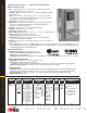
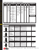
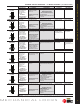
HOW TO ORDER
&
=
>
%"
MS– magnetic
stripe
PM– proximity
Motorola
PH– proximity
HID
MSA– other
cylinder
PHA– other
cylinder
PMA– other
cylinder
45HM–
IDH Max™
0– Keyless
or less
cylinder,
7– 7 pin
housing
ONLY
605 606
611 612
613 618
619 625
626 690
RH
RHRB
LH
LHRB
**Must specify key mark and number of keys or designate L/C for less core.
†
See H Series catalog for details.
KNL
(page 11)
Series
45HM 7
Core
Housing
DEU 14
Function
Lever/Knob
Style
MS 626
Trim
Style
Finishes
†
RH
Handing
Options
†
(page 11)(page 5)
SH – se cu ri ty head screws
TAC – tactile lever
Thick
Door – specify thick ness if
other than 1
3
/
4
"
7/8" LTC– flat lip strike
1300 – B.A.S.I.S. direct
connect
(page 3)
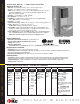
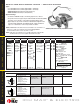
Case— Heavy wrought steel, 5
7
⁄
8
" H x 4
1
⁄
4
" D x 1" W steel parts are zinc
dichromate plated for cor ro sion pro tec tion.
Faceplate— Brass or bronze, 1
1
⁄
4
" x 8" x
7
⁄
32
" . Armored. Adjustable from flat
to beveled
1
⁄
8
" - 2" .
Strike— Brass, bronze or Stainless Steel, 4
7
⁄
8
" x 1
1
⁄
4
" x
3
⁄
32
". Fits standard
door frame cut out as spec i fied in ANSI A115.1.Correct strike automatically
supplied with unit. Strike box supplied standard.
Door thickness— For doors 1
3
⁄
4
" – 4" thick.
Installation— Lock requires modified door prep to mount the trim. Faceplate
di men sions fit stan dard door prep a ra tion as specified in ANSI A115.1,.
Lockset is re vers ible for hand of door.
Latchbolt— Stainless steel,
3
⁄
4
" throw with anti-friction latch.
Deadbolt— Solid stainless steel, 1" throw.
Auxiliary bolt— Stainless steel.
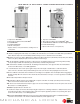
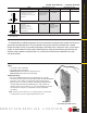
Die cast trim housing—Dimensions: 10
3
⁄
8
" H x 3
1
⁄
4
" W x 1" D sloping down to
3
⁄
4
".
Knobs— Diameter: 2
1
⁄
8
" Projection on door: 2
7
⁄
8
"
#4, #6 knobs: Material machined from brass or bronze.
Lever handle— Brass, bronze or stainless steel. (Lever #3, #14 and #15
conform to California Titles 19 and 24.)
Mounting— Knob and lever attached with hardened set screw on inside knob or
inside lever.
Finish— 605-bright brass, clear coated; 606-satin brass, clear coated; 611-bright bronze, clear coated; 612-satin bronze, clear
coated; 613-oxidized satin bronze, oil rubbed; 625-bright chromium plated; 626-satin chromium plated; 629-bright stainless
steel; 630-satin stainless steel; 690-dark bronze.
"
Maximum current draw: 1.1 Amp for 50 milliseconds
Typical current draw (hold condition): 650 milliAmps
Voltage: 10.2 to 13.2 V (DC only)
Operating Temperature: Minimum/Maximum range Inside: 70˚± 4˚F (21˚± 2˚C) Outside: -31˚F (-35˚C) to +151˚F (+66˚C)
Magnetic Stripe Card Reader:
Read Rate: 5 inches per second to 50 inches per second.
Card thickness: ISO standard .030"
±
.003 thick.
Compliance to FCC, Canadian, and European EMC requirements; for interference FCC Class A digital ap pa ra tus.
Magnetic Stripe adaptation: Trim option that can accept other manufacturers cylinder.
Proximity Reader:
ANSI/BHMA A156.25 compliant. Compatible with Motorola / Indala and HID proximity cards. ABA and Wiegand output.
Weatherproof bezel and gasket provide protection for outdoor use. (Usable in all environmental/exterior applications)
Card Read Range: 0 – 3 inches. Compliance to US FCC, Canadian FCC, and European EMC requirements
ESD Protection:15 Kilo Volt
&
=
468/7,
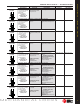
Levers
3– solid tube return
12– solid tube
14– curved return
15– curved angle
return
16– curved no return
17– gullwing no
return
Knobs
4– round
DEL– electrically
locked
DEU– electrically
unlocked
NXEL– electrically
locked
NXEU– electrically
unlocked
TDEL– electrically
locked
TDEU– electrically
unlocked
LEL– electrically
locked
LEU– electrically
unlocked