
Specifications

14
IDH Max
®
& ELECTRO
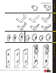
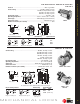
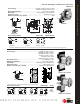
ELECTRIC sWITCH LOCk – INTRODUCTION
Stanley Security Solutions offers a line of electric switch locks available in various “on-off” and “mo men tary” keyed switch func tions.
Circuitry vari a tions are available in single, double and triple pole with varied voltage and amperage ratings. Units may be keyed
into any BEST system. The BEST in ter change able core offers ver sa til i ty and adapt abil i ty for new and existing electrical controls,
panels, machines, etc.
Features
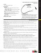
• Double D lock cylinder prevents slipping and turning
• Screw terminals on all switch locks (except the 1W7A1) provides ease of installation
• All switches are UL recognized or listed
Note on functionality: Switch lock keys can only be removed in the 12 o’clock position.
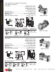
How to select a switch lock
1. Determine the electrical requirements for the device being controlled:
A. Voltage (for example: 115 VAC or 24 VDC)
B. Current or horsepower (for example: 6 amps or
1
/
2
horsepower)
C. Type of load
• Resistive (for example, heat er elements)
• Inductive (for example, mo tors, large transformers)
• Lamp (for example, in can des cent lights)
2. Determine the switch configuration (poles and throws) and key re mov al condition:
A. Poles To determine the number of poles, find how many wires from the power source need to be switched on and off by the
switch lock.
B. Throws To determine the number of throws, find how many wires to the device the switch needs to control. For example, if a
switch needs two different “on” conditions (low and high speed), two throws are needed. Or if the device is simply an “on-off”
type (only one wire), you need one throw.
Note: A switch throw may be left unwired and used as an “off” condition.
C. Key removal To determine the key removal condition, ask the question, “When the key is removed, should the switch be
“off”, or could the switch be either “on” or “off” ?” Although the key can only be removed in the 12 o’clock position, the switch
itself may be left in two or three positions. Check each switch lock for key removal switch positions.
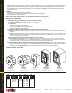
3. Use the information collected and find the switch lock that best meets the requirements. Refer to the following catalog
pages for a de scrip tion of each switch lock. If en vi ron men tal conditions make it necessary that the switch lock be housed in an
electrical box, see the Optional boxes (above) for the box that best suits the switch lock and your application.
" !%" > " #"
!%
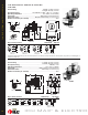
Standard weather
resistant box
4
5
/
8
" x 2
7
/
8
" x 2
1
/
4
"
"
Interior box
4" x 2
1
/
8
" x 1
7
/
8
"
%
Deep weather
resistant box
4
5
/
8
" x 2
7
/
8
" x 3"
Deep octagon
offset mount
3
1
/
2
" x 3
1
/
2
" x 3
1
/
4
"
Standard octagon
center mount
3
1
/
2
" x 3
1
/
2
" x 1
5
/
8
"
"&!
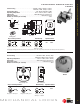
OPTIONaL bOxEs
1W 7– 7 pin housing
accepts all
BEST cores
see pages
15–19
605 606
611 612
613 619
622 625
626 690
see above
1W 7 B1 626
Series Core
Housing
Func tion
Finishes
SWR
HOW TOORDER
%" >%" !%"
Box