IDH Max® & ELECTROMECHaNICaL LOCks IDH Max® & ELECTROMECHaNICaL LOCks
IDH Max® – INTRODUCTION IDH Max® – fEaTUREs TabLE Of CONTENTs Page IDH MAX® introduction ........................................................2 IDH MAX® features ..............................................................2 IDH Max® and IDH Max® 1300 comparison chart ................3 HM, KM, HW & KW options..................................................3 40HM IDH MAX® specifications, how-to-order ....................4 40HM IDH MAX® functions ..................................................
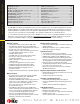
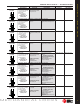
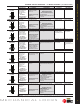
* ** IDH MAX® 1. Prep door for IDH MAX® 2. Run single 4 conductor wire for IDH MAX® 3. Install IDH MAX® 4. Install electrified hinge 5. Mount control panel IDH MAX® 1300 1. Prep door for IDH MAX® 2. Run single 4 conductor wire for IDH MAX® 1300 3. Install IDH MAX® 1300 which includes Intelligent System 4. Install electrified hinge IDH Max® COMPaRIsON CHaRT IDH MAX® & IDH MAX® 1300 coMPARISon cHART ** Operates with B.A.S.I.S. control panels only.
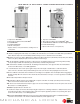
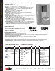
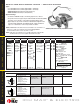
0HM IDH Max® sPECIfICaTIONs 40HM IDH MAX® – SPEcIFIcATIonS MEcHAnIcAl Case— Heavy wrought steel, 5 7⁄8" H x 4 1⁄4" D x 1" W steel parts are zinc dichromate plated for corrosion protection. Faceplate— Brass or bronze, 1 1⁄4" x 8" x 7⁄32" . Armored. Adjustable from flat to beveled 1⁄8" - 2" . Strike— Brass, bronze or Stainless Steel, 4 7⁄8" x 1 1⁄4" x 3⁄32". Fits standard door frame cut out as specified in ANSI A115.1.Correct strike automatically supplied with unit. Strike box supplied standard.
Function DEL–Locked Fail Safe Latch Operated by • Outside knob/lever when power is removed from the solenoid • Outside key • Inside knob/lever. Latchbolt is deadlocked by an auxiliary latch Outside Knob/Lever Unlocked by Locked by Applying power to the solenoid; remains locked while power is on. Inside Knob/Lever Locked by Unlocked by Removing power from the solenoid Cannot be locked Always unlocked Powered by 12V DC. temperature control module is not needed.
9kM IDH Max® – sPECIfICaTIONs 9KM IDH MAX® – SPEcIFIcATIonS MEcHAnIcAl Materials— Internal parts are brass, zinc or corrosion-treated steel. Chassis— 2 1⁄16" diameter to fit 2 1⁄8" diameter hole in door. Strike— Brass or bronze, 4 7⁄8" x 1 1⁄4" x 3⁄32". Fits standard door frame cut out as specified in ANSI A115.1. Correct strike automatically supplied with unit. Strike box supplied standard. Backset— 2 3⁄4" standard, 3 3⁄4" and 5" available.
• Rotating the inside knob/lever, • Rotating the outside knob/lever— only when power is off, • Turning the key in the outside knob/lever. Applying 12 volts DC. The outside knob/lever remains locked only while power is on. Switching off 12 volts DC Cannot be locked Always unlocked Cannot be locked Always unlocked Powered by 12V DC. Temperature control module (TCM) is not needed.
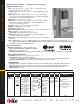
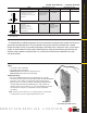
40HW ELECTRIfIED – HOW TO ORDER 40HW ElEcTRIFIED – HoW To oRDER 45HW Series 7 Core Housing 45HW: 45HW– lever 47HW– lever 0– keyless or less high security cylinder, 7– 7 pin 47HW: 7– 7 pin (accepts 5C cores only) NXEU Function 12 Lever Style J Trim Style 45HW/47HW: DEL– single key latch, fail safe DEU– single key latch, fail secure WEL– double key latch, fail safe WEU– double key latch, fail secure TDEL– single key deadbolt, fail safe TDEU– single key deadbolt, fail secure TWEL–double key deadbolt, f
TDEL–Locked Fail Safe TDEU–Unlocked Fail Secure TWEL–Locked Fail Safe TWEU–Unlocked Fail Secure NXEL–Locked Fail Safe NXEU–Unlocked Fail Secure LEL–Locked Fail Safe LEU–Unlocked Fail Secure Applying power to solenoid; Removing power from solenoid Cannot be locked Always unlocked • Outside key • Outside knob/lever remains locked while when power is power is on Deadbolt and latchbolt removed from the retracted simultaneously by: solenoid.
8kW/9kW – sPECIfICaTIONs 8KW & 9KW ElEcTRIFIED locKS – SPEcIFIcATIonS 8kW/9kW – HOW TO ORDER 8KW & 9KW ElEcTRIFIED locKS – HoW To oRDER Types: • 12 volts AC/DC when used with supplied TCM — 0.50 amps • 24 volts AC/DC when used with supplied TCM — 0.18 amps • All EU functions: Electrically Unlocked (Fail Secure) • All EL functions: Electrically Locked (Fail Safe) Approval Listings: • UL listed for GYQS Electrically-controlled singlepoint locks or latches.
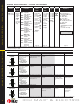
#4 knob #12 lever C rose D rose K rose L rose EScUTcHEon TRIM VARIATIonS J escutcheon M escutcheon N escutcheon MS escutcheon MECHaNICaL LOCks ROsEs TRIMs S rose cYlInDRIcAl RoSE TRIMS EsCUTCHEON TRIM MoRTISE RoSE TRIMS R rose #17 lever #16 lever #15 lever H rose #14 lever LEVER sTyLEs #6 knob lEVER STYlES #3 lever kNObs KnoB STYlES Prox escutcheon 11
8W599 ElEcTRIFIED AccESSoRIES 8W599 Features: • • • • • • • • • Offers exceptionally high power for its compact size UL listed Thermally fused Convenient 4 point mounting provision allows rapid installation in a standard 1/2" knockout Foot-mounts for surface installation Pre-stripped pigtails provided for quick primary connection Secondary connection by screw terminals Sturdy nylon bobbin construction Cadmium plated finish Transformer Specifications: 8WCON Primary voltage: 120 VAC (Wire Leads) Second
8WTcM Features • All circuitry completely sealed Wire leads: Input– 24 AWG – Stranded wire with PVC insulation (approx. 60" in length) Output– 24 AWG – Stranded wire with Teflon insulation (approx. 2.6" in length) Input: 12 or 24 volts AC or DC @ at 0.50 or 0.18 amp Output: Voltage out @ 1 amp maximum for 0.5 seconds then 30% of voltage out for 5 seconds Output protection: Short circuit current limiting set at one (1) amp.
ELECTRIC sWITCH LOCk – INTRODUCTION OPTIONaL bOxEs HOW TOORDER 14 ElEcTRIc SWITcH locK – InTRoDUcTIon Stanley Security Solutions offers a line of electric switch locks available in various “on-off” and “momentary” keyed switch functions. Circuitry variations are available in single, double and triple pole with varied voltage and amperage ratings. Units may be keyed into any BEST system.
1W7A1 Contacts ..............................................................................................Silver or gold flash Contact rating ..........................................................................28 VDC, 10 amps resistive 28 VDC, 3 amps inductive, lamp 125 VAC, 10.1 amps resistive 250 VAC, 10.1 amps resistive Horsepower rating ..................................................................................125 VAC, 1/4 HP Operating temperature .......................................
1W ELECTRIC sWITCH LOCks 1W ElEcTRIc SWITcH locKS 1W7B2 & 1W7J2 Contact rating .................................................................. 30 VDC, 15 amps, resistive 125 VDC, 0.6 amps, resistive 250 VDC, 0.3 amps, resistive 125 VAC, 15 amps, resistive 125 VAC, 5 amps, lamp 250 VAC, 15 amps, resistive Horsepower rating ......................................................................125–250 VAC, 1/2 HP Operating temperature ..............................................................
1W7D2 Contact rating . . . . . . . . . . . . . . . . . . . . . . . . . .110 VAC or VDC, 16 amps, resistive 220 VAC or VDC, 8 amps, resistive Horsepower rating . . . . . . . . . . . . . . . . . . . . . . . . . . .1 HP @ 125–250 VAC or VDC Operating temperature . . . . . . . . . . . . . . . . . . . . . . .0°F to +150°F (-18°C to +66°C) Switch type . . . . . . . . . . . . . . . . . . . . . . . . . . . . . . .DPST (Double pole-single throw) Switch lock action . . . . . . . . . . . . . . . . . . . . . . . . . .
1W ELECTRIC sWITCH LOCks 1W ElEcTRIc SWITcH locKS 1W7E2 Contact rating 110 VAC, 15 amps, resistive 220 VAC, 10 amps, resistive Horsepower rating 125–250 VAC or VDC, 3/4 HP; 1, 2, or 3 phase Operating temperature ........................................................0 to +150°F (-18°C to 66°C) Switch type ....................................................................TPDT (Triple pole-double throw) Switch lock action ............................................
Contact rating ..........................................................110 VAC or VDC, 12 amps, resistive 220 VAC or VDC, 6 amps, resistive Operating temperature ..................................................................up to +221°F (+105°C) Switch type ....................................................................SPDT (Single pole-double throw) Switch lock action ..............................................................................
IDH Max® & ELECTROMECHaNICaL LOCks For more information on Stanley Security Solutions’ products, services, and office locations visit our web site at www.stanleysecuritysolutions.com Product information contained in this catalog has been compiled and presented with as much care and completeness as is reasonably possible.