FACILITIES DIVISION – DESIGN SERVICES M E M O R A N D U M TO: PREQUALIFIED BIDDERS FROM: CHUCK ROGERS, DESIGN PROJECT MANAGER AUBURN UNIVERSITY FACILITIES DIVISION PROJECT: PHARMACY CARE SYSTEMS / 11-201 DATE: 4/3/2012 CC: MARK ADERHOLDT / FILE Addendum No. 1 Please find the attached Addendum No. 1 for the above referenced project. This information becomes part of the Bid Set Contract Documents upon receipt. Please review and incorporate provided information into your bid accordingly.
Auburn University Pharmacy Care Systems / Foy Hall AU Project No. 11-201 Addendum No. 1 April 3, 2012 ADDENDUM NO. 1 General This Addendum to the Contract Documents is issued prior to award of Contract. Project Manual 1. Remove the Table of Contents in its entirety and replace with revised Table of Contents (attached herein). Changes to the document are noted in italic type. 2. Remove the Special Conditions, in its entirety and replace with revised Special Conditions. (attached herein). 3.
Auburn University Pharmacy Care Systems / Foy Hall AU Project No. 11-201 Addendum No. 1 April 3, 2012 Drawings 1. Remove the following drawings in their entirety and replace with new drawings as indicated in the List of Drawings on Sheet A0.0. Changes to drawings include addition of abatement design, renumbering of rooms, and HVAC ductwork change. A0.0 General Project Information / Drawing Index / General Notes A0.1 Existing Conditions & Demolition Plan A0.2 Life Safety Plan A1.
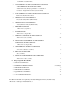
TABLE OF CONTENTS (AU FUNDED) SINGLE PRIME CONTRACTS (Revised January 2012) Pharmacy Care Systems Foy Hall Basement Project 11-201 I. Proposal Documents A. Standard Documents 1. INSTRUCTIONS TO BIDDERS ABC Form C-2 (Aug. 2001) 2. PAGES SUPPLEMENTAL INSTRUCTIONS TO BIDDERS 9 2 AU Form C-2 SIB (November 2011) 3. SALES AND USE TAX EXEMPTION AU Form C-2A SUTE (April 2011) 4. PROPOSAL FORM ABC Form C-3 (Aug. 2001) 5. 2 FORM OF BID BOND ABC Form C-4 (Aug. 2001) 6.
AU FORM C-5A (March 2002) 3. ATTACHMENT B TO THE CONSTRUCTION CONTRACT ATTACHMENT B: HEALTH AND SAFETY Auburn University Safety Specification – Construction Contracts – Single Prime Contract (October 2010) 4. 12 #ATTACHMENT C TO THE CONSTRUCTION CONTRACT AU Form C-5B (December 2011) 5. 1 APPENDIX A TO ATTACHMENT B Project Site Safety Plans (March 2010) 6. 3 APPENDIX B TO ATTACHMENT B Activity Hazard Analysis (March 2010) 7. 3 PERFORMANCE BOND 3 ABC Form C-6 (April 2011) 8.
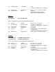
SPECIAL CONDITIONS 1. TIME OF COMPLETION Work in this contract shall be substantially completed by August 1, 2012, assuming the Notice to Proceed is issued as stated below. 2. NOTICE TO PROCEED The intended Notice to Proceed is May 1, 2012. In the event that the NTP is later than the stated date, the date of Substantial Completion shall be increased the same number of days the NTP is issued beyond the above date. 3. LIQUIDATED DAMAGES See Section 49 of the ABC Form C-8, General Conditions. 4.
AUBURN UNIVERSITY – PHARMACY CARE SYSTEMS ARCHITECTS PRE-LIMINARY HARDWARE SCHEDULE – 03.30.12 IT’S THE VENDORS RESPONSIBILITY TO REVIEW THE ARCHITECTS DRAWINGS AND MODIFY THE SCHEDULE AND CUT SHEETS AS REQUIRED. HEADINGS ARE REFERENCED ON THE DOOR SCHEDULE DRAWING A1.0. HEADING 1 1 SGL DOOR C104 RECEPTION/WAIT RHR TYPE B - (V.I.F.) X (V.I.F.
HEADING 3 1 SGL DOOR 131B OFFICE LHR TYPE B - (V.I.F.) X (V.I.F.) FLUSH INSULATED METAL DOOR X HM WELDED FRAME 3 EA 3 EA 1 EA 1 SET 1 EA 1 EA 1 EA 1 EA HINGES SILENCERS THRESHOLD JAMB SEAL HEAD SEAL DOOR SWEEP DEADLOCK MORTISE CYLINDER HAGER ROCKWOOD PEMKO PEMKO PEMKO PEMKO ADAMS RITE ADAMS RITE BB1279 X 4.5 X 4.
1 EA POWER SUPPLY VONDUPRIN PS861 (AUBURN TO VERIFY SPEC. & OPTIONS) 1 EA 1 EA KICKPLATE CARD READER ROCKWOOD BEST K1038 X 12” X 34” X CSK X S. STEEL IDH MAX (SPEC. PROVIDED BY AUBURN) SEE NOTES & COMMENTS BELOW. HEADING 7 1 SGL DOOR 156 GRAD STUDENTS RH TYPE A - 3/0X7/0 FLUSH SCWD DOOR X HM WELDED FRAME 3 EA 1 EA HINGES PASSAGE SET HAGER BEST/STANLEY 1 EA 3 EA 1 EA WALL STOP SILENCERS CLOSER ROCKWOOD ROCKWOOD LCN 1 EA KICKPLATE ROCKWOOD BB1279 X 4.5 X 4.
INOX - GENERAL NOTES & COMMENTS 1. Control sample to be provided to Architect for review and approval. 2. Flush doors will be furnished as VT Industries 5502 series or equal with particleboard core. 3. Interior hollow metal frame will be furnished as 16 gauge, welded, primed for field painting. All doors and frames to have a sprayed vs. brushed final finish. 4. Contractor to verify transitions and doors to be undercut. Where ventilation is required doors to be undercut ½”. 5. See A1.
Exterior Doors: LCN 4041 Series (No Substitutions Allowed) Interior Doors: LCN 1461 Series (No Substitutions Allowed) All door closers shall be mounted on the interior side of the room. All door closers shall be equipped with “Delayed Action” feature. 8) All lock hardware must accept BEST 7 pin, interchangeable cores. 9) All interior door hardware shall be BEST 45H mortise or 9K cylindrical locks. 10) All access control system control panels shall be mounted within a telecom closet.
HEAVY DUTY LOCKS - LEVERS HEAVY DUTY CYLINDRICAL LOCKS – LEVERS
TABLE OF CONTENTS & FEATURES TABLE OF CONTENTS Page Features ..............................................................2 Specifications ..............................................................3 How to Order ..................................................................3 Trim Variations ..............................................................4 Options/Features ................................................5 Service Equipment ......................................................
Latch – Solid brass 9/16" throw. Front 2 1/4" x 1 1/8" beveled. Lever handles – Lever handles are a high-quality zinc alloy. Trim components are brass or bronze. Body is approximately 1 5/8" in diameter; Handle is approximately 4 3/4" long (from center-line of chassis). #14 and #15 levers conform to California Administrative Code Title 19 and Title 24. All three styles of levers conform to the Illinois Accessibility Standard. American National Standard: ANSI A156.
TRIM VARIATIONS DIMENSIONS 4 TRIM VARIATIONS 14C 15C 16C 14D 15D 16D 14K 15K 16K 14L 15L 16L LEVER & TRIM DIMENSIONS H E AV Y D U T Y L
SERVICE EQUIPMENT KD303 THROUGH-BOLT DRILL JIG Special accessory jig aids in aligning 5/16" holes for through-bolt mounting. Install the latch first, then insert jig in 2 1/8" bored hole, align with door edge and drill with 5/16" drill bit. A drill jig is included 1 per every 9 locksets with your order. Additional jigs are available upon request. To order: designate KD303. KD303-9K KD304A BORING JIG KITS The KD304A jig kit is made for boring cut outs in wooden doors for ANSI A156.
FUNCTIONS FUNCTIONS Function & Diag. (ANSI No.) Single Keyed Entrance AB F109 Storeroom D Description Latch operated by Outside Lever Locked by Unlocked by • Rotating the inside lever, • Pushing the inside button, • Rotating the outside • Pushing and turning the lever—only when the inside inside button.
Function & Diag. (ANSI No.
FUNCTIONS FUNCTIONS Function & Diag. (ANSI No.) Description Latch operated by Electromechanical • Rotating the inside lever, Electrically Locked • Rotating the outside lever only when power is off, DEL Locked by Outside Lever Unlocked by • Applying 24 Volts DC.
Function & Diag. (ANSI No.
SAMPLE SPECIFICATIONS ACCEPTABLE MANUFACTURERS A. Locksets and Latchsets Stanley/Best - No Substitution. 1. 2. 3. 4. 5. 6. 7. 8. 9. Locksets and latchsets: ANSI A156.2, Series 4000, Grade 1 UL listed, extra heavy-duty cylindrical type. Backset 2 3/4 inches (70mm) Interchangeable core 7-pin: [Restricted keyway] [Patented] [Standard] [ ]. Locksets to have anti-rotational studs that are through-bolted. Keyed lever with no exposed keeper hole.
How to Order (page 3). 8KL5 Deadlocking Latch Bolt throw– 9/16" Backset– 5" Front– 2 1/4" x 1 1/8" beveled. Tube– To fit 1" diameter hole in door edge. To order: (with unit) designate “95K” on How to Order (page 3). To order: (without unit) designate “8KL3-SL” To order: (without unit) designate “8KL4-SL" To order: (without unit) designate “8KL5-SL” (Spring Latch) or DL (Deadlocking Latch) and finish. (Spring Latch) or DL (Deadlocking Latch) and finish.
HEAVY DUTY CYLINDRICAL LOCKS – LEVERS For more information on Stanley Security Solutions’ products, services, and office locations visit our web site at www.stanleysecuritysolutions.com Product information contained in this catalog has been compiled and presented with as much care and completeness as is reasonably possible.
Designed for maximum CLOSER MOUNTS *HINGE (PULL) SIDE TOP JAMB (PUSH SIDE) PARALLEL ARM (PUSH SIDE) versatility, the 1460, available with multiple cover options, can be used for both commercial and institutional applications. This fully universal closer offers a wide variety of options and new fast and accurate installation. UL and cUL listed for self-closing doors without hold-open. Tested and certified under ANSI Standard A156.4, grade one.
MOUNTING DETAILS LCN 1460 SERIES HINGE (PULL) SIDE MOUNTING MAXIMUM OPENING 110° A = 5 7/8” (149 mm) B = 10 7/8” (276 mm) or *180° A = 2 7/8” (73 mm) B = 7 7/8” (200 mm) Hold-open points up to maximum opening with hold-open arm. *Frame and trim permitting. Optional, Non-handed Designer Series Metal Cover Butt Hinges should not exceed 5” (127 mm) in width. Auxiliary Stop is recommended at hold-open point or where a door cannot swing 180°.
TOP JAMB (PUSH SIDE) MOUNTING MAXIMUM OPENING 110° A = 6 3/4” (169 mm) B = 11 1/4” (286 mm) 180° A = 3” (76 mm) B = 7 1/2” (191 mm) Hold-open points up to maximum opening with hold-open arm. 1460 - 18 Optional, Non-handed Designer Series Metal Cover Butt Hinges should not exceed 5” (127 mm) in width. Auxiliary Stop is recommended at hold-open point or where a door cannot swing 180°. Reveal of 2 1/2” (64 mm) allows 180° opening with REGULAR HOLD-OPEN ARM.
MOUNTING DETAILS LCN 1460 SERIES PARALLEL ARM (PUSH SIDE) MOUNTING Optional mounting requires PA SHOE, 1460-62PA for REGULAR or HOLDOPEN arms. Add prefix "P" to closer description (e.g. P1461). P1461 closer includes 1460-201 FIFTH HOLE SPACER to support PA SHOE. MAXIMUM OPENING Regular or hold-open arm can be templated for 100° A = 4 1/4” (108 mm) B = 9 1/4 (235 mm) or 180°. A = 1 3/4” (44 mm) B = 6 3/4” (171 mm) 1460 - 18PA Hold-open points up to maximum opening with hold-open arm.
1460 EDA MOUNT 1460 EDA or CUSH-N-STOP MOUNTING 1460 closers ordered with EDA, CUSH arms include 1460-201 FIFTH HOLE SPACER to support the shoe. MAXIMUM OPENING EDA template allows 110°. Hold-open point up to maximum opening. CUSH arms can be templated for maximum opening/hold-open point at 85°, A = 2 3/8” (60 mm) B = 9 9/16” (243 mm) 90°, A = 1 5/8” (41 mm) B = 9 1/16” (230 mm) or 100°.
ACCESSORIES LCN 1460 SERIES CYLINDERS CYLINDER, 1460-3071 Standard, non-handed cast iron cylinder assembly. 3071 ARMS REGULAR ARM, 1460-3077 Non-handed arm mounts hinge side or top jamb. P1460 closer includes PA SHOE, 1460-62PA required for parallel arm mounting. PA SHOE, 1460-62PA Required for parallel arm mounting. LONG ARM, 1460-3077L Optional, non-handed arm includes LONG ROD AND SHOE, 1460-79LR for top jamb mount with deep reveals.
COVERS 72 72DS1 COVER, 1460-72 Standard, non-handed, slim line plastic cover with feature strip. 72FC FULL COVER, 1460-72FC Optional, non-handed, plastic cover provides complete enclosure. 18DS1 18 18FC DESIGNER SERIES METAL COVER, 1460-72DS1 Optional, non-handed designer series metal full cover provides complete enclosure with a stylish look. Required for plating and custom powder coat option.
HOW-TO-ORDER 1460 SERIES CLOSERS ORDERING INFORMATION LCN 1460 SERIES TABLE OF SIZES Select closer based on width of door. The spring power of a 1461 cylinder is field adjustable from size 1 through size 6 and is shipped adjusted to size 3. Indicates recommended range of door width for closer size.
LCN 4040 SERIES The 4040 SUPER SMOOTHEE® is CLOSER MOUNTS HINGE (PULL SIDE) (Shown) TOP JAMB (PUSH SIDE) PARALLEL ARM (PUSH SIDE) LCN’s most flexible heavy duty closer designed for institutional and other rugged high traffic applications.
LCN 4040 SERIES 4040XP The 4040XP is LCN’s most durable heavy duty closer designed for the most demanding, high use and abuse applications. 4040XP Non-sized cylinder is adjustable for interior doors to 5’0” and exterior doors to 4’0”. Closer mounts parallel arm (EDA arm) on either right or left swinging doors. Optional hinge side and top jamb mount with optional regular arm. Closers to meet ADA requirements. See 4040XP Series page 49. Standard or optional custom powder coat finish.
LCN 4040 SERIES HINGE (PULL) SIDE MOUNTING MAXIMUM OPENING Templating allows up to 120°. Hold-open points 90° up to 120° with hold-open arm. Butt Hinges should not exceed 5” (127 mm) in width. Auxiliary Stop is recommended at hold-open point or where a door cannot swing beyond 120°. Reveal should not exceed 3/4” (19 mm) for regular arm or hold-open arm. Options 4040XP cylinder 4041 Delayed action cylinder. Hold-open arm. Metal cover.
LCN 4040 SERIES TOP JAMB (PUSH SIDE) MOUNTING MAXIMUM OPENING Templating allows up to 120°. Hold-open points 85° up to 120° with hold-open arm. Butt Hinges should not exceed 5” (127 mm) in width. Auxiliary Stop is recommended at hold-open point or where the door cannot swing 120°. Reveal of 2 9/16” (65 mm) allows 120° opening for REGULAR ARM or standard HOLD-OPEN ARM. 4 13/16” (122 mm) allows up to 120° opening with LONG ARM where standard rod and shoe is replaced with optional LONG ROD AND SHOE 4040-79LR.
LCN 4040 SERIES PARALLEL ARM (PUSH SIDE) MOUNTING Optional mounting requires PA SHOE, 4040-62PA for REGULAR or HOLDOPEN arms. Add prefix "P" to closer description (eg. P4041). P4041 closer includes 4040-201 FIFTH HOLE SPACER to support PA SHOE. MAXIMUM OPENING 180° opening/hold-open points with all except CUSH arms. 110° opening/hold-open with CUSH arms. Butt Hinges should not exceed 5” (127 mm) in width.
LCN 4040 SERIES Mounting details are the same as 4040 Series REGULAR or HOLDOPEN except as listed below. 4040 Series closers ordered with EDA or CUSH arms include 4040201 FIFTH HOLE SPACER to support the shoe. 4040 SERIES EDA MOUNT MAXIMUM OPENING EDA arm can be templated for points at: 110°, A = 6 3/8” (162 mm) B = 7 3/4” (197 mm) or 180°. A = 2 7/8” (73 mm) B = 4 1/4” (108 mm) Hold-open points up to maximum opening with HEDA arm.
LCN 4040 SERIES CYLINDERS 3071XP CYLINDER, 4041-3071 Standard, non-handed cast iron cylinder assembly. CYLINDER, 4040XP-3071 Heavy duty, non-handed cast iron cylinder assembly. 3071 COVERS COVER, 4040-72 Standard, non-handed plastic clip-on cover. METAL COVER, 4040-72MC Optional, handed cover. Required for plated finishes and custom powder coat finishes. 72 72MC 62PA ARMS REGULAR ARM, 4040-3077 Non-handed arm mounts pull side or top jamb with shallow reveal.
LCN 4040 SERIES ARMS cont. 3077CNS CUSH-N-STOP® ARM, 4040-3077CNS Optional, non-handed parallel arm features solid forged steel main arm and forearm with stop in soffit shoe. HCUSH ARM, 4040-3049CNS Provides hold-open function with templated stop/hold-open points. Handle controls hold-open function. 3049CNS SPRING CUSH ARM, 4040-3077SCNS Optional, non-handed parallel arm for abusive applications features solid forged steel main arm and forearm with spring loaded stop in the soffit shoe.
LCN 4040 SERIES INSTALLATION ACCESSORIES cont. CUSH SHOE SUPPORT, 4040-30 provides anchorage for fifth screw used with CUSH arms, where reveal is less than 3 1/16” (78 mm). 30 61 BLADE STOP SPACER, 4040-61 required to lower parallel arm shoe to clear 1/2” (13 mm) blade stop. 61 PA FLUSH PANEL ADAPTER, 4040-419 provides horizontal mounting surface for PA or CUSH shoe on single rabetted or flush frame. AUXILIARY SHOE, 4040-62A requires a top rail of 7” (178 mm).
LCN 4040 SERIES TABLE OF SIZES 4041 cylinders are adjustable from size 1 through size 6 and is shipped set to size 3. Closing power of 4040 series closers may be adjusted 50%. Indicates recommended range of door width for closer size. EXTERIOR (and VESTIBULE) DOOR WIDTH 30" 762mm 24" 610mm size 3 size 5 1. SELECT FINISH. Standard Powder Coat __________ Aluminum, Dark Bronze , Statuary, Light Bronze, Black, Brass.
LCN 4040 SERIES TABLE OF SIZES 4040XP cylinders are adjustable from size 1 through size 6 and is shipped set to size 3. Closing power of 4040 series closers may be adjusted 50%. Indicates recommended range of door width for closer size. EXTERIOR (and VESTIBULE) DOOR WIDTH 30" 762mm 24" 610mm size 3 size 5 1. SELECT FINISH. Standard Powder Coat __________ Aluminum, Dark Bronze , Statuary, Light Bronze, Black, Brass.
IDH MAX® & ELECTROMECHANICAL LOCKS IDH MAX® & ELECTROMECHANICAL LOCKS
IDH MAX® – INTRODUCTION IDH MAX® – FEATURES TABLE OF CONTENTS Page IDH MAX® introduction ........................................................2 IDH MAX® features ..............................................................2 IDH Max® and IDH Max® 1300 comparison chart ................3 HM, KM, HW & KW options..................................................3 40HM IDH MAX® specifications, how-to-order ....................4 40HM IDH MAX® functions ..................................................
* ** IDH MAX® 1. Prep door for IDH MAX® 2. Run single 4 conductor wire for IDH MAX® 3. Install IDH MAX® 4. Install electrified hinge 5. Mount control panel IDH MAX® 1300 1. Prep door for IDH MAX® 2. Run single 4 conductor wire for IDH MAX® 1300 3. Install IDH MAX® 1300 which includes Intelligent System 4. Install electrified hinge IDH MAX® COMPARISON CHART IDH MAX® & IDH MAX® 1300 COMPARISON CHART ** Operates with B.A.S.I.S. control panels only.
40HM IDH MAX® SPECIFICATIONS 40HM IDH MAX® – SPECIFICATIONS MECHANICAL Case— Heavy wrought steel, 5 7⁄8" H x 4 1⁄4" D x 1" W steel parts are zinc dichromate plated for corrosion protection. Faceplate— Brass or bronze, 1 1⁄4" x 8" x 7⁄32" . Armored. Adjustable from flat to beveled 1⁄8" - 2" . Strike— Brass, bronze or Stainless Steel, 4 7⁄8" x 1 1⁄4" x 3⁄32". Fits standard door frame cut out as specified in ANSI A115.1.Correct strike automatically supplied with unit. Strike box supplied standard.
Function DEL–Locked Fail Safe Latch Operated by • Outside knob/lever when power is removed from the solenoid • Outside key • Inside knob/lever. Latchbolt is deadlocked by an auxiliary latch Outside Knob/Lever Unlocked by Locked by Applying power to the solenoid; remains locked while power is on. Inside Knob/Lever Locked by Unlocked by Removing power from the solenoid Cannot be locked Always unlocked Powered by 12V DC. temperature control module is not needed.
9KM IDH MAX® – SPECIFICATIONS 9KM IDH MAX® – SPECIFICATIONS MECHANICAL Materials— Internal parts are brass, zinc or corrosion-treated steel. Chassis— 2 1⁄16" diameter to fit 2 1⁄8" diameter hole in door. Strike— Brass or bronze, 4 7⁄8" x 1 1⁄4" x 3⁄32". Fits standard door frame cut out as specified in ANSI A115.1. Correct strike automatically supplied with unit. Strike box supplied standard. Backset— 2 3⁄4" standard, 3 3⁄4" and 5" available.
• Rotating the inside knob/lever, • Rotating the outside knob/lever— only when power is off, • Turning the key in the outside knob/lever. Applying 12 volts DC. The outside knob/lever remains locked only while power is on. Switching off 12 volts DC Cannot be locked Always unlocked Cannot be locked Always unlocked Powered by 12V DC. Temperature control module (TCM) is not needed.
40HW ELECTRIFIED – HOW TO ORDER 40HW ELECTRIFIED – HOW TO ORDER 45HW Series 7 Core Housing 45HW: 45HW– lever 47HW– lever 0– keyless or less high security cylinder, 7– 7 pin 47HW: 7– 7 pin (accepts 5C cores only) NXEU Function 12 Lever Style J Trim Style 45HW/47HW: DEL– single key latch, fail safe DEU– single key latch, fail secure WEL– double key latch, fail safe WEU– double key latch, fail secure TDEL– single key deadbolt, fail safe TDEU– single key deadbolt, fail secure TWEL–double key deadbolt, f
TDEL–Locked Fail Safe TDEU–Unlocked Fail Secure TWEL–Locked Fail Safe TWEU–Unlocked Fail Secure NXEL–Locked Fail Safe NXEU–Unlocked Fail Secure LEL–Locked Fail Safe LEU–Unlocked Fail Secure Applying power to solenoid; Removing power from solenoid Cannot be locked Always unlocked • Outside key • Outside knob/lever remains locked while when power is power is on Deadbolt and latchbolt removed from the retracted simultaneously by: solenoid.
8KW/9KW – SPECIFICATIONS 8KW & 9KW ELECTRIFIED LOCKS – SPECIFICATIONS 8KW/9KW – HOW TO ORDER 8KW & 9KW ELECTRIFIED LOCKS – HOW TO ORDER Types: • 12 volts AC/DC when used with supplied TCM — 0.50 amps • 24 volts AC/DC when used with supplied TCM — 0.18 amps • All EU functions: Electrically Unlocked (Fail Secure) • All EL functions: Electrically Locked (Fail Safe) Approval Listings: • UL listed for GYQS Electrically-controlled singlepoint locks or latches.
#4 knob #12 lever C rose D rose K rose L rose ESCUTCHEON TRIM VARIATIONS J escutcheon M escutcheon N escutcheon MS escutcheon MECHANICAL LOCKS ROSES TRIMS S rose CYLINDRICAL ROSE TRIMS ESCUTCHEON TRIM MORTISE ROSE TRIMS R rose #17 lever #16 lever #15 lever H rose #14 lever LEVER STYLES #6 knob LEVER STYLES #3 lever KNOBS KNOB STYLES Prox escutcheon 11
8W599 ELECTRIFIED ACCESSORIES 8W599 Features: • • • • • • • • • Offers exceptionally high power for its compact size UL listed Thermally fused Convenient 4 point mounting provision allows rapid installation in a standard 1/2" knockout Foot-mounts for surface installation Pre-stripped pigtails provided for quick primary connection Secondary connection by screw terminals Sturdy nylon bobbin construction Cadmium plated finish Transformer Specifications: 8WCON Primary voltage: 120 VAC (Wire Leads) Second
8WTCM Features • All circuitry completely sealed Wire leads: Input– 24 AWG – Stranded wire with PVC insulation (approx. 60" in length) Output– 24 AWG – Stranded wire with Teflon insulation (approx. 2.6" in length) Input: 12 or 24 volts AC or DC @ at 0.50 or 0.18 amp Output: Voltage out @ 1 amp maximum for 0.5 seconds then 30% of voltage out for 5 seconds Output protection: Short circuit current limiting set at one (1) amp.
ELECTRIC SWITCH LOCK – INTRODUCTION OPTIONAL BOXES HOW TOORDER 14 ELECTRIC SWITCH LOCK – INTRODUCTION Stanley Security Solutions offers a line of electric switch locks available in various “on-off” and “momentary” keyed switch functions. Circuitry variations are available in single, double and triple pole with varied voltage and amperage ratings. Units may be keyed into any BEST system.
1W7A1 Contacts ..............................................................................................Silver or gold flash Contact rating ..........................................................................28 VDC, 10 amps resistive 28 VDC, 3 amps inductive, lamp 125 VAC, 10.1 amps resistive 250 VAC, 10.1 amps resistive Horsepower rating ..................................................................................125 VAC, 1/4 HP Operating temperature .......................................
1W ELECTRIC SWITCH LOCKS 1W ELECTRIC SWITCH LOCKS 1W7B2 & 1W7J2 Contact rating .................................................................. 30 VDC, 15 amps, resistive 125 VDC, 0.6 amps, resistive 250 VDC, 0.3 amps, resistive 125 VAC, 15 amps, resistive 125 VAC, 5 amps, lamp 250 VAC, 15 amps, resistive Horsepower rating ......................................................................125–250 VAC, 1/2 HP Operating temperature ..............................................................
1W7D2 Contact rating . . . . . . . . . . . . . . . . . . . . . . . . . .110 VAC or VDC, 16 amps, resistive 220 VAC or VDC, 8 amps, resistive Horsepower rating . . . . . . . . . . . . . . . . . . . . . . . . . . .1 HP @ 125–250 VAC or VDC Operating temperature . . . . . . . . . . . . . . . . . . . . . . .0°F to +150°F (-18°C to +66°C) Switch type . . . . . . . . . . . . . . . . . . . . . . . . . . . . . . .DPST (Double pole-single throw) Switch lock action . . . . . . . . . . . . . . . . . . . . . . . . . .
1W ELECTRIC SWITCH LOCKS 1W ELECTRIC SWITCH LOCKS 1W7E2 Contact rating 110 VAC, 15 amps, resistive 220 VAC, 10 amps, resistive Horsepower rating 125–250 VAC or VDC, 3/4 HP; 1, 2, or 3 phase Operating temperature ........................................................0 to +150°F (-18°C to 66°C) Switch type ....................................................................TPDT (Triple pole-double throw) Switch lock action ............................................
Contact rating ..........................................................110 VAC or VDC, 12 amps, resistive 220 VAC or VDC, 6 amps, resistive Operating temperature ..................................................................up to +221°F (+105°C) Switch type ....................................................................SPDT (Single pole-double throw) Switch lock action ..............................................................................
IDH MAX® & ELECTROMECHANICAL LOCKS For more information on Stanley Security Solutions’ products, services, and office locations visit our web site at www.stanleysecuritysolutions.com Product information contained in this catalog has been compiled and presented with as much care and completeness as is reasonably possible.
12-3/16 x 17-13/16 x 11-9/16 For answers to your Monogram,® GE Profile™ or GE® appliance questions, visit our website at geappliances.com or call GE Answer Center® service, 800.626.2000. Note: This unit designed to be placed on countertop. *Height includes feet. Depth does not include handle HxWxD Exterior Dimensions* Dimensions and Installation Information (in inches) GE® 0.7 Cu. Ft.
• Model JE740DRBB – Black • Model JE740DRWW – White • C ooking complete reminder - Lets you know when your food has finished cooking • K itchen timer - Oven timer can be set to countdown a specific amount of minutes to help watch the time for you • C ontrol lockout - Provides peace of mind by locking the oven and preventing accidental activation • I nstant on controls - Cooking and reheating happens instantly at the touch of a button • Turntable - Rotates food throughout the cooking cycle for e
"" * &) 6" " &) $ " $ , " $ ) 7 " 6" " 6" " 7 / % ) & 6&$ 6" " : & ' : & ' 7 ; * ( - ') !" " : ' 8 96 9 6&$ - "% $ " 0 * 6&$ ! '" & 6" " *"$+ "' $ ') 6" " "' $ ') % 5" / <)) "44 *" ! <)) ! " #
!"#$ !""! #% & ' #() %(!" ( # "( !**+ ! ,( &!-." !""! #% & ' #() %(!" ( # "( !**+ ! ,( !""! #% .#($ (( /" ##( /!""! #% 0.
27 Case depth without door (in.) C† 1/2 1/2 Top (in.) Back (in.) For answers to your Monogram,® GE Profile™ or GE® appliance questions, visit our website at ge.com or call GE Answer Center® service, 800.626.2000. Note: Top-Freezer No-Frost Left-Hand Refrigerator Doors: As you face the front of the refrigerator, the handle is on your right and the hinges are on your left.
• Model GTH21KCXBB - Black on black • Model GTH21KCXWW - White on white • Deluxe quiet design - Significantly reduces unnecessary operating noise in the kitchen • NeverClean™ condenser - Sealed compartment keeps coils clean and simplifies maintenance • Wire freezer shelves - Sturdy shelves provide additional storage for frozen foods • Upfront temperature controls - A simple knob turn regulates interior temperatures with ease • Snack drawer - Conveniently stores favorite foods and allows for quick
Counter Support Bracket Information & Installation ® Rakks Counter support brackets come in a variety of sizes, configurations and finishes to provide sturdy and unobtrusive support for counters, work surfaces, vanities and benches. 7 max Surface Mounted Installation Rakks Counter Support Brackets can carry significant loads but they must be securely fastened to the wall. With continuous blocking, or double-stud construction, brackets can be spaced as much as 4 feet apart.
Counter Support Bracket Information & Installation ……..Continued Preparation and Application of Drywall 3 7/8” 3 7/8” Face Plate for 2” x 2” T EHFP-0202 Face Plate for 2” x 3” T EHFP-0203 To provide for a fully recessed installation, the drywall must be installed and patched around the bracket supporting arm. Once the drywall has been installed, it should be plastered around the bracket to provide a finished installation.
Architectural Series Fire Extinguisher Cabinets Submittal and Detail Sheet PHARMACY CARE SYSTEMS PROJECT:_____________________________ MODEL NUMBER:_______________________ INOX DESIGN,INC. ARCHITECT:___________________________ 01.10.
CABINET DIMENSIONS - ARCHITECTURAL SERIES Model Number ◆ Trim Style and Projection Inside Box Dimensions Outside Trim Dimensions** Recommended Extinguisher Rough Opening*** Height Width Depth Height Width Height Width Depth Capacity __ 2409-R1 __ 2409-5R __ 2409-R3 Rec. 5/16" Semi-Rec. 1½" Semi-Rec.
Technical Data ClassicSeries® SURFACE-MOUnTED PAPER TOWEL DISPENSER B-2620 Finish Face of Wall 10-13/16" 275mm 3-15/16" 7-1/2" S 190mm S 100mm Knob Latch 265mm S S 54'' 1370mm 10-7/16" 66" to 70" 1675 to 1780mm 355mm S Recommended Mounting Height Off Floor For Barrier-Free Design 14-1/16" Door Recommended Mounting Height Off Floor S MATERIALS: Cabinet — 18-8 S, type-304, 22-gauge (0.8mm) stainless steel with satin finish. All-welded construction. Exposed surfaces have satin finish.
Technical Data ClassicSeries® SURFACE-MOUNTED SOAP DISPENSER B-2111 4-3/4'' S S Finish Face of Wall Filler-Top S 8-1/8'' 205mm Concealed Wall Plate S Window Push Button & Spout 2-3/4'' 70mm 50-7/8'' 1290mm S Recommended Mounting Height Off Floor For Universal / Barrier-Free Design 120mm 3-1/2'' 90mm MATERIALS: Container — 18-8 S, type-304, 22-gauge (0.8mm) stainless steel with satin-finish. Body is drawn, one-piece, seamless construction. Back plate has mounting bracket attached.
Catalog Number Notes Type FEATURES & SPECIFICATIONS INTENDED USE — The Avante 2x4 is a general lighting luminaire for large spaces including open offices, circulation areas, classrooms, libraries, cafeterias, airport ticketing and wait areas, and numerous other commercial applications. Static or air functions available. Certain airborne contaminants can diminish integrity of acrylic. Click here for Acrylic Environmental Compatibility table for suitable uses.
2AV 2x4 Direct/Indirect Lighting 2AV G 2 32 MDR, (2) 32W T8 lamps, 2850 lumens per lamp, s/m 1.2 (along) 1.3 (across), test no.
Lithonia Lighting - The best value in lighting Home Company Resources Training Distributors Sales Sustainability Contact Lithonia Lighting Products Commercial & Industrial Fluorescent Fluorescent and LED High Bay Special Applications Indoor HID Emergency Downlighting & Track Outdoor Decorative Indoor & Outdoor Contractor Select LED Lighting ABL Wiring and Controls RELOC Wiring Solutions Synergy Lighting Controls Additional ABL Companies Resources Specification Sheets Photometri
Lightvent Cerra® Lightvent With a pure crescent shape, parallel baffled openings and perforated side walls to soften the fixture and provide a luminous form, Cerra® Lightvent from Peerlite delivers soft, even illumination for office and school lighting applications. Cerra® Lightvent is available in the petit Cerra® 7 family and the architecturally refined Cerra® 10 family. Construction Finish Electrical Specify 7" x 2" or 10"x3" crescent channel formed from one-piece coldrolled steel.
Catalog Number Notes Type FEATURES & SPECIFICATIONS 1-3/4" deep design uses T8 or T12 lamps. Undercabinet Light Ideal for work stations and under cabinets, unit or row mounting. 2UC Low brightness, linear prism acrylic lens standard. Convenience outlet and on/off rocker switch available. Diffuser snaps easily into fixture body flanges. Certain airborne contaminants can diminish integrity of acrylic. Click here for Acrylic Environmental Compatibility table for suitable uses.
2UC Undercabinet Light MOUNTING DATA DIMENSIONS Inches (centimeters). Subject to change without notice. Lithonia Lighting Sheet #: 2UC ©1996-2010 Acuity Brands Lighting, Inc., All rights reserved, Rev. 7/12/10 Fluorescent One Lithonia Way, Conyers, GA 30012 Phone: 800-858-7763 www.lithonia.
Catalog Number Notes Type INOX DESIGN FEATURES & SPECIFICATIONS INTENDED USE Ideal for a wide variety of low- to medium-height ceiling applications including commercial, retail and hospitality spaces where an open or damp location lensed fixture is required. CONSTRUCTION Heavy gauge die formed galvanized steel mounting frame. Attached to frame are vertically adjustable mounting brackets for use with C channels, ½” steel conduit or 16 gauge flat bar hangers included, standard.
6” LF6N Horizontal 1-Lamp, Triple Tube (TRT), Open Distribution Curve Distribution Data Output Data Coefficient of Utilization Illuminance Data at 30” Above Floor for a Single Luminaire LF6N 1/32TRT F6O1AZ MVOLT, (1) Philips PL-C 32W/27SH lamp, 1.2 s/mh, 2400 rated lumens, Test no. LTL12515 cp 90˚ 100 70˚ 200 300 50˚ 400 500 600 10˚ 30˚ 0 5 15 25 35 45 55 65 75 85 90 598 612 639 533 471 444 137 11 3 1 0 Lumens 59 178 247 296 330 135 12 3 1 Zone Lumens % Lamp 0˚ - 30˚ 483.7 20.
FORTÉ® Features • • • • • • • • KITCHEN SINK FAUCET Metal construction One-piece, self-contained ceramic disc valve allows both volume and temperature control Temperature memory allows faucet to be turned on and off at any temperature setting High-temperature limit setting for added safety 9-1/16″ (23 cm) swing spout reach Flexible supplies Lower flow aerator options are available (refer to the Kohler Price Book) 2.2 gpm (8.
FORTÉ® Installation Notes Install this product according to the installation guide. ADA, CSA B651, OBC compliant when installed to the specific requirements of these regulations. 9-1/16" (23 cm) 8-7/8" (22.5 cm) 7-7/8" (20 cm) 6-1/8" (15.6 cm) 17" (43.2 cm) 10" (25.4 cm) 4" (10.2 cm) 4" (10.2 cm) Cold Supply Hoses with 3/8" Compression Fittings Product Diagram FORTÉ® KITCHEN SINK FAUCET Page 2 of 2 1022761-4-E 2-1/2" (6.4 cm) 1-3/8" (3.
MIDDLETONTM Features • • • • • SELF-RIMMING KITCHEN SINK 14711 SilentShieldTM sound deadening Self-rimming Rolled rim 25″ (63.5 cm) x 22″ (55.9 cm) x 8″ (20.
MIDDLETONTM Technical Information Installation Notes Install this product according to the installation guide. Fixture*: Sink cutout size basin area 24-1/2″ (62.2 cm) x 21″ (53.3 cm) 21-1/2″ (54.6 cm) with x 15-1/4″ 1/2″ (1.3 cm) radius (38.7 cm) corners. Drain hole 3-5/8″ (9.2 cm) D. Faucet holes 1-7/16″ (3.7 cm) D. * Approximate measurements for comparison only. 14711-4 14711-3 4" 8-1/2" (10.2 cm) 4-1/16" (21.6 cm) (10.3 cm) 2-9/16" (6.5 cm) 8-1/2" (21.6 cm) 2-13/16" (7.1 cm) 4" (10.