
Specification Guide


PROF366RTBXT
PROFESSIONAL SERIES
36" GAS RANGETOP 6 BRASS BURNERS
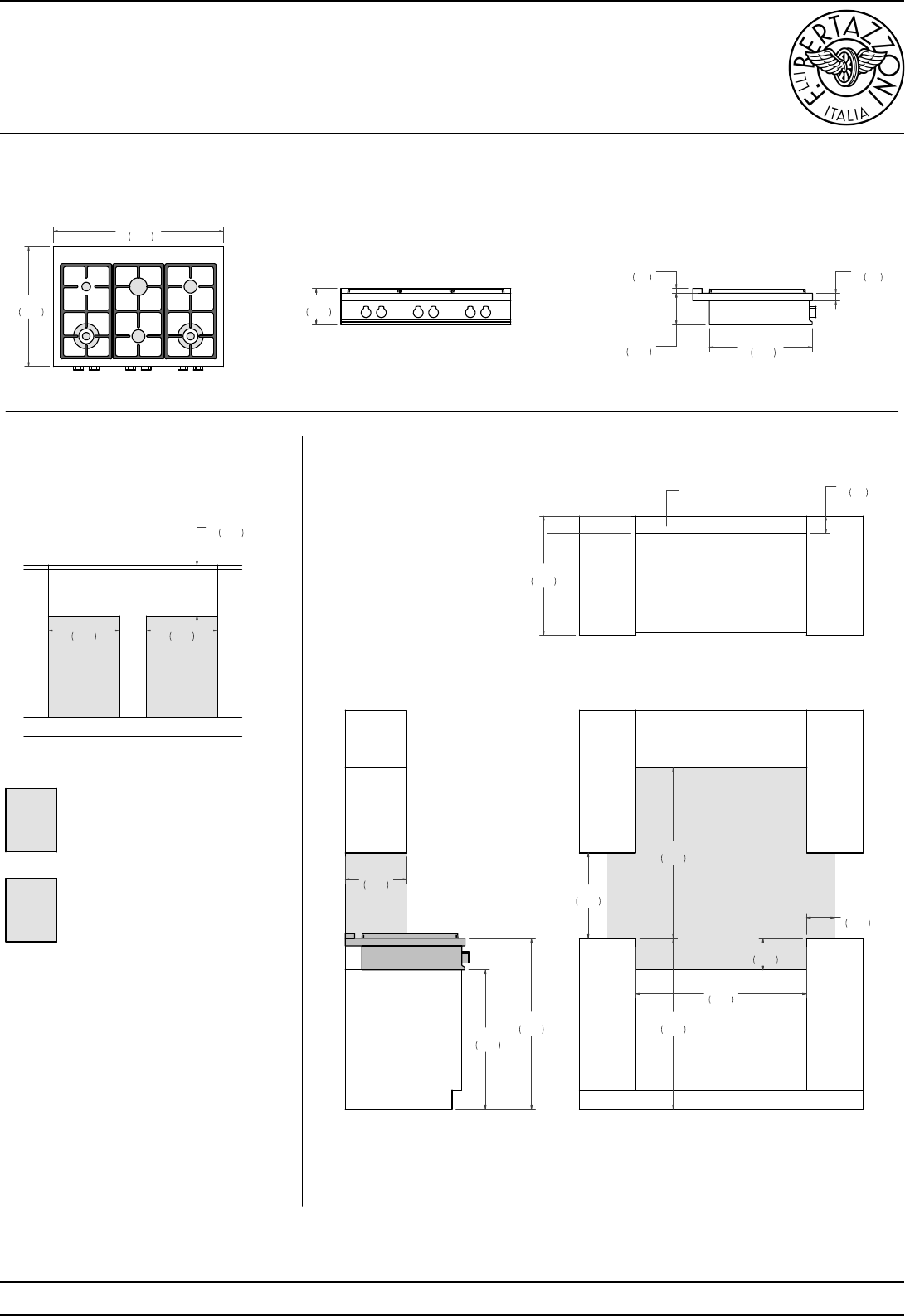
TOP VIEW
FRONT VIEW
SIDE VIEW
PRODUCT DIMENSIONS
CUTOUT DIMENSIONS ELECTRICAL & GAS
CONNECTION
SIDE VIEW FRONT VIEW
TOP VIEW
INSTALLATION
REQUIREMENTS
A
n agency-approved,
properly-sized manual
shut-off valve should be
installed according to this
drawing.
A
properly-grounded,
horizontally-mounted electrical
receptacle should be installed
according to this drawing.
E
G
Combustible material cannot be
installed within shaded area.
For installation with an updraft or
downdraft hood as well as any OTR,
refer to the hood/OTR manufacturer’s
installation requirements.
18"
457
36"
915
13"
330
6"
152
36"
913
6 5/8"
168
25"
635
3 1/2"
90
25 1/4"
641
35 3/4"
909
6 5/8"
168
1"
26
7 5/8"
194
21 5/8"
550
36"
914
1 5/8"
40
29 3/8"
746
36"
915
E
G
10 5/8"
270
COUNTERTOP
15"
381
15"
381
AREA FOR ELECTRIC
AND GAS CONNECTION
For installation of multiple products in combination, refer to the Design Guide at us.bertazzoni.com or ca.bertazzoni.com
Disclaimer: while every effort has been made to ensure the accuracy of the information contained in this document, Fratelli Bertazzoni reserves the right to change it at any time without notice.
For detailed installation instructions, consult the installation manual. Fratelli Bertazzoni, Bertazzoni and the winged wheel brand icon are registered trademarks of Bertazzoni Spa.
bertazzoni.comversion: 1