RP551+/RP651+ Interactive Flat Panel User Manual
Disclaimer BenQ Corporation makes no representations or warranties, either expressed or implied, with respect to the contents of this document. BenQ Corporation reserves the right to revise this publication and to make changes from time to time in the contents thereof without obligation to notify any person of such revision or changes. Copyright Copyright 2014 BenQ Corporation. All rights reserved.
Table of Contents i Table of Contents Safety warnings and precautions ...................................... 1 Important safety instructions............................................ 2 Notes on the LCD panel of this display..................................... 2 Safety notice for remote control................................................. 3 Battery safety notice ....................................................................... 3 BenQ ecoFACTS...................................................
ii Table of Contents Operations in the OSD menu.................................................... Picture menu ................................................................................. Sound menu.................................................................................... Screen menu .................................................................................. Setting menu ..................................................................................
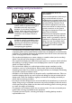
Safety warnings and precautions 1 Safety warnings and precautions The lightning flash with arrowhead symbol, within an equilateral triangle, is intended to alert the user to the presence of uninsulated "dangerous voltage" within the product's enclosure that may be of sufficient magnitude to constitute a risk of electric shock to persons.
2 Important safety instructions Important safety instructions 1. 2. 3. 4. 5. 6. 7. 8. 9. 10. 11. 12. 13. 14. Read these instructions. Keep these instructions. Heed all warnings. Follow all instructions. Do not use this apparatus near water. Clean only with dry cloth. Do not block any ventilation openings. Install in accordance with the manufacturer's instructions. Do not install near any heat sources such as radiators, heat registers, stoves, or other apparatus (including amplifiers) that produce heat.
Important safety instructions 3 screen as visible fixed lines and shades. To avoid such damage to the screen, avoid displaying still images (like On-Screen Display menus, TV station logos, fixed/inactive text or icons) for more than two hours. Change the aspect ratio from time to time. Fill the entire screen with the image and eliminate the black bars whenever possible.
4 Important safety instructions BenQ ecoFACTS BenQ has been dedicated to the design and development of greener product as part of its aspiration to realize the ideal of the "Bringing Enjoyment 'N Quality to Life" corporate vision with the ultimate goal to achieve a low-carbon society.
Package contents 5 Package contents Open the sales package and check the contents. If any item is missing or damaged, please contact your dealer immediately.
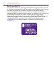
6 Setting up the display Setting up the display Attaching the pen tray and I/O box Before mounting and using the display, please follow the steps below to install the pen tray and I/O box. The installation should be performed by at least two adult persons to avoid danger and injuries. 1. Place a clean, dry and lint-free cloth on a flat, horizontal and object-free surface. Make sure that the size of the cloth is larger than the display. 2.
Setting up the display 7. Connect one end of the supplied audio interface cable (the end with a 3.5mm Mini-jack plug and two RCA-type plugs) to the AUDIO IN (AUDIO1) and AUDIO IN (AUDIO2) input jacks on the rear panel of the display, and the other end (the end with a 3.5mm Mini-jack plug) to the audio interface jack on the I/O box. 8. Route the cables properly using the cable clips.
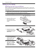
8 Setting up the display Mounting the display You can install the display on a vertical surface with a suitable wall mounting bracket or on a horizontal surface with the optional desktop stands. Please pay attention to the following notes during installation: • This display should be installed by at least two adult persons. Attempting to install this display by only one person may result in danger and injuries. • Refer the installation to qualified technicians.
Setting up the display • To maintain proper ventilation, keep at least 10 mm of clear space from the back cover of the display to the wall. • Please consult a professional technician for wall mount installations. The manufacturer accepts no liability for installations not performed by a professional technician. 10mm (0.39") • The AC IN/OUT socket should be on top of connectors when rotating your display. Installing the optional desktop stands 1.
10 Parts of the display and their functions Parts of the display and their functions Front/Rear panel 1 2 RP551+ 3 4 5 6 7 RP651+ No. Name Description 1 • Receives command signals from the remote control. • Detects ambient lighting conditions around the display and adjusts screen brightness automatically when the Ambient Light Sensor function is activated. • Indicates the operating status of the display: - Lights up green when the power is turned on.
Parts of the display and their functions 11 5 , , /-, /+ • Scrolls through settings and options in the OSD menu. • /-, /+: Hot keys for audio volume adjustment. 6 Power button Turns the display on or off. Power indicator Indicates the power status of the display: - Lights up green when the power is turned on. - Lights up red when the display is turned off. - Lights up red when the display is in Power Save High mode. - Flashes red when the display is in Power Save Low mode.
12 Parts of the display and their functions Input/output terminals RP551+ RP651+ RJ-45 19 USB Type A 17 MULTI-MEDIA USB Type A HDMI MIC IN 22 21 20 DP 16 MULTI-MEDIA USB Mini-B 18 HDMI 15 VIDEO IN RS-232C OUT AV VGA Y Pb OUT AUDIO IN AUDIO IN AUDIO OUT AUDIO 1 AUDIO 2 IN Pr No. 100-240V~50-60Hz AC SWITCH ON/OFF 3.4A 3 2 IN IN 13 12 11 10 Name R 9 8 7 6 5 4 AC OUT (1.7A) Relays the AC power from the AC IN jack to another display. 2 AC IN (3.
Parts of the display and their functions 12 13 14 13 Receives S-Video signals from an external device (such as a VCR or DVD player). Receives component video (YPbPr) signals from an external device VIDEO IN (YPbPr) (such as a DVD player, HDTV device or Laser disc player). For external control and multi-display operation. • RS232C IN: receives control signals from a computer or another display. RS232C IN/OUT • RS232C OUT: outputs control signals from the RS232C IN input to another display.
14 Parts of the display and their functions Remote control 5 ENTER Confirms your selection or save changes. 1 6 2 6 INFO Shows the current input source and resolution. 7 Numeric buttons (1-9) /Input source buttons 7 3 8 9 4 10 5 • Performs as numeric buttons when the OSD menu is on. • Performs as input source buttons when the OSD menu is off. The DVI and SDI functions are not available with this display. 8 9 11 MENU Opens or closes the OSD menu.
Parts of the display and their functions 15 Using the remote control Installing remote control batteries 1. Open the remote control battery compartment cover. 2. Insert the supplied batteries ensuring that the positive and negative marked battery terminals match the (+) and (-) marks in the battery compartment. The supplied batteries are provided for your convenience so that you can operate the display straight away. You should replace them as soon as possible. 3. Refit the battery compartment cover.
16 Connection Connection Connecting audio/video signals Pay attention to the following notes when you connect cables: • Please turn off all devices. • Familiarize yourself with the audio/video ports on the display and the devices you want to use. Be aware that incorrect connections may adversely affect picture quality. • Do not remove cables from the ports by pulling the cable itself. Always grasp and pull the connectors at the end of the cable.
Connection 17 Connecting the digital inputs 1. Connect the HDMI output jack of a computer or A/V device (such as a VCR or DVD player) to the HDMI input jack on the display using an HDMI cable. If the device has a DisplayPort output jack, connect it to the display’s DP input jack using a DisplayPort cable. 2. If the DisplayPort connection is used, connect the audio output jack of the device to the AUDIO IN (AUDIO1) jack on the display using a suitable audio cable.
18 Connection Connecting the YPbPr component video input 1. Connect the VIDEO IN (YPbPr) jacks on the display to the component output jacks on an A/V device (such as a VCR or DVD player) using a component video cable. 2. Connect the DVD player’s audio output jacks to the AUDIO IN (AUDIO2) jacks on the display using a suitable audio cable. 3. To view video image from this input, press the YPbPr button on the remote control. To select an appropriate audio source, see Audio Source on page 35 for details.
Connection 19 Connecting the AV and S-Video inputs 1. Connect the VIDEO IN (S-VIDEO) or AV IN jack on the display to the output jack on an A/V device (such as a VCR) using an appropriate video cable. 2. Connect the VCR’s audio output jacks to the AUDIO IN jacks on the display using a suitable audio cable. 3. To view video image from this input, press the AV button on the remote control for the AV signal, or press the INPUT button repeatedly for the S-Video signal.
20 Connection Connecting the multimedia inputs To connect to a network, do one of the following steps. • Take a RJ-45 cable and connect one end to the RJ-45 jack on the display and the other end to the RJ-45 port on your Ethernet or router. • Plug a wireless dongle to the USB Type A jack. To connect to a computer directly: Take a USB cable, connect the mini B plug to the USB Mini-B jack on the display and the type A plug to a computer.
Connection 21 Connecting multiple displays You can connect multiple displays serially (daisy chain) to a computer for management. The number of displays you can connect serially depends on the resolution of the input signal you use. Additional display VIDEO IN RS-232C OUT RJ-45 Pb IN Pr OUT VIDEO IN Pb AV VGA OUT DP HDMI AUDIO IN AUDIO IN AUDIO OUT AUDIO 1 AUDIO 2 USB TYPE B FOR TOUCH AC SWITCH ON/OFF 3.4A L OUT Pr 3.4A IN 1.
22 Connection Connecting the touch module Connect the USB TYPE B FOR TOUCH (type B) jack on the display to the USB port of a computer using the supplied USB cable. The touch module of the display supports easy Plug-and-Play operation. There is no need to install additional drivers on the computer. VIDEO IN RS-232C OUT RJ-45 Pb AV VGA Y OUT USB Type A IN DP HDMI Pr AUDIO IN AUDIO IN AUDIO OUT AUDIO 1 AUDIO 2 USB TYPE B FOR TOUCH AC SWITCH ON/OFF 100-240V~50-60Hz 3.4A IN 1.
Connection 23 Connecting power 1. Plug one end of the power cord into the AC IN jack on the display and the other end into an appropriate power outlet (if the outlet is switched, turn on the switch). 2. Flip the power switch to the ON position to turn on the main power. 2 1 • The supplied power cord is suitable for use with 110-240V AC power only. • The power cord and outlet illustrated may differ from the ones used in your region. • Only use an appropriate power cord for your region.
24 Using the touch screen Using the touch screen You can use the optical touch screen to control your operating system. The touch screen can emulate basic mouse functions and supports multi-touch functions for Windows 7/ 8*. The following table shows a list of gestures you can use on the touch screen. • Ensure that you have installed the USB cable on the display to a computer.
Using the touch screen OS functions Gesture actions For Windows Vista and Windows 7 Drag one finger left or right. Selection Quickly drag your finger (Flick) in a desired direction. Pan up / Pan down / Back / Forward Multi-touch functions For Windows 7 - Home Premium, Professional, Enterprise and Ultimate versions 1. Press on the target. 2. Tap the screen with another finger. 3. Release the second finger. Right-click Drag one or two fingers up or down.
26 Using the touch screen OS functions Gesture actions • Move two fingers in opposing directions. • Use one finger to pivot around another. Supported by specific applications Tap two fingers simultaneously. The target should be the midpoint between the fingers. Supported by specific applications For Windows XP, Windows Vista and Windows 7 Press and hold for 4 seconds.
Using the touch screen Gesture 27 Description Slide to pan Slide is primarily used for panning interactions but can also be used for moving, drawing or writing. Slide can also be used to target small, densely packed elements by scrubbing (sliding the finger over related objects such as radio buttons). Swipe to select, command, and move Sliding the finger a short distance, perpendicular to the panning direction, selects objects in a list or grid (ListView and GridLayout controls).
28 Using the touch screen Important instructions for using the touch screen Please clean the frame when there is sign of malfunction on the touch screen. • Before you clean the screen, make sure the display is turned off, and unplug the power cord. • Remove dust or dirt from the screen and the infrared plastic filter periodically. It is suggested using a small amount of alcohol to clean the infrared plastic filter.
Basic operations 29 Basic operations Turning the display on or off To turn on or off the display, press the power button on the display’s control panel or on the remote control. • The display’s standby mode still consumes power. To completely cut off power supply, set the power switch to the off position or disconnect the power cord from the power outlet. • The display follows the VESA approved DPM Power Management function.
30 Network connection Network connection Connecting to a LAN To set the display to connect to a local area network: 1. Connect a RJ45 cable to the corresponding ports on the display and your LAN switch or router. 2. Enter the OSD menu Setting > Control Setting. Select LAN. 3. Enter the next OSD menu Setting > Network Settings. If you are in a DHCP environment, select DHCP > Execute and press ENTER.
Network connection IP address Main menus 31
32 The OSD (On-Screen Display) menu The OSD (On-Screen Display) menu OSD menu overview Menu name Picture Sound Screen Setting Options/functions • Picture Mode • Backlight • Contrast • Brightness • Chroma • Phase • Sharpness • Color Temp.
The OSD (On-Screen Display) menu 33 Operations in the OSD menu Using the control panel buttons 1. Press MENU to open the OSD menu. Using the remote control 1. Press MENU to open the OSD menu. ENTER VIDEO SOURCE 2. In the OSD menu, press or to select an item. 2. Press or to select an item. ENTER VIDEO SOURCE 3. Press ENTER/VIDEO SOURCE to confirm selections. 3. Press ENTER to confirm selections. ENTER TER VIDEO SOURCE 4.
34 The OSD (On-Screen Display) menu Picture menu Picture Picture Mode Backlight Standard 100 50 50 25 25 10 Cool Mid Auto Contrast Brightness Chroma Phase Sharpness Color Temp. Noise Reduction Film Mode Reset :Move Name Picture Mode Backlight Contrast Brightness Chroma Phase Sharpness Color Temp. Noise Reduction ENTER :Enter EXIT :Exit Description Sets the display mode. Adjusts the backlight intensity for the screen.
The OSD (On-Screen Display) menu 35 Sound menu Sound Sound Mode Treble Bass Balance Surround Speaker Audio Source Reset :Move Standard 0 0 Center Off Internal Audio1 ENTER :Enter Name EXIT :Exit Description Adjusts the sound output from the speakers. • Dynamic: Enhances treble and bass. Sound Mode • Standard: Flat settings. • Custom: Recalls the customized settings. Treble Adjusts the audio treble. Bass Adjusts the audio bass. Balance Adjusts the audio balance.
36 The OSD (On-Screen Display) menu Screen menu Screen PAP Setting Aspect Adjust Screen Freeze Touch Feature :Move Full Off Off ENTER :Enter Name EXIT :Exit Description • PAP: Turns on or off the PIP (Picture in Picture) and PBP (Picture by Picture) functions. • Active Picture: For the PIP, selects the main or sub picture to operate. For the PBP, selects the left or right picture to operate. Swaps the main/ sub or left/right pictures. • Picture Size: Changes the size of the sub picture.
The OSD (On-Screen Display) menu 37 • Picture Position: (PIP only) Changes the position of the sub picture. PAP Setting (Continued) Upper Left Upper Right Lower Left Lower Right • PAP is not available for all signal source combinations. See Supported PAP input signal combination on page 65 for more information on supported combinations. • In PAP mode, only sound from the active picture will be available. Sets the picture’s aspect ratio. • Wide Zoom: Enlarges to fill screen with minimum distortion.
38 The OSD (On-Screen Display) menu Full Full 4:3 4:3 For PC signal input Real Full 1 Aspect (continued) Adjust Screen Freeze Full 2 • Auto Adjustment: Sets whether to optimize image display for each VGA input. • Phase: Adjusts the phase of the VGA input image. • Clock Frequency: Adjusts the clock frequency of the VGA input image. • H. Position: Adjusts the horizontal position of the VGA input image. • V. Position: Adjusts the vertical position of the VGA input image.
The OSD (On-Screen Display) menu 39 Setting menu Setting Language Schedule Power Save Control Setting Network Settings Set Monitor ID HDMI Control Advanced Information All Reset :Move Name Language ENTER :Enter English High RS-232C 1 Off EXIT :Exit Description Sets your preferred language for the OSD menu. • Date and Time: Sets the current date and time. • Clock Display: Sets whether to show the current time which was set. • On/Off Timer: Sets when to turn on or off the display.
40 The OSD (On-Screen Display) menu Control Setting • RS-232C/LAN: Sets a terminal to control the display. • IR Passthrough: Select it when multiple displays are connected via RS-232C cables. - Primary: Designate the display as the primary unit for remote control operation. Only this display will be operated by the remote control. - Secondary: Designate the display as the secondary unit.
The OSD (On-Screen Display) menu 41 • OSD Rotation: Adjusts the OSD rotation. See product specifications for models recommended for portrait orientation. Landscape only models operated in portrait mode may result in premature failure and will not be covered under the warranty. Advanced • OSD Info Box: When turned On, switching signal inputs, or changing timing, the display will show the current input source and resolution onscreen.
42 Multimedia OSD operation Multimedia OSD operation The multimedia OSD system provides a variety of settings when the display is connecting to USB devices, wireless networks, or using the built-in storage device, etc. To access the multimedia OSD system: 1. Make sure the display is correctly connecting to a multimedia device. See Connecting the multimedia inputs on page 20 for details. 2.
Multimedia OSD operation 43 Viewing files • Files on the built-in storage device The display is built-in an approximate 3GB storage device. To transfer files to the display, you need to take a USB cable, connect the type A plug to your computer and connect the mini B plug to the display. Once connected, locate the Removable Disk on your computer. Select and drag the target files from your computer to the Removable Disk. Make sure the files are completely transferred to the display.
44 Multimedia OSD operation Remote control key function in browse mode No 1 Icon Description Rotation • Press / /ENTER to rotate the picture clockwise (0 > 90 > 180 > 270). 2 • Press / to rotate the picture counterclockwise (0 > 270 > 180 > 90 > 0). Zoom • Press ENTER to zoom in/out on the picture. • Press (PREV) (NEXT) to navigate the picture. 3 Previous photo 4 Next photo 5 Slideshow mode 6 Press ESC/ENTER/ (PREV) browse mode.
Multimedia OSD operation 45 • Video: Lists all supported files. Select the video you want to display and perform the functions as provided on the screen according to your needs. Remote control key function in list view No Name Description 1 HOME Goes back to the main page. 2 ESC Goes back to the previous page. 3 ENTER Opens the selected video. • 4 (PREV) 5 REV (NEXT) • / : Sorts items by file names (alphabetically) or created time. • : Shows subtitle files for the selected item.
46 Multimedia OSD operation Control user interface Remote control key function: when the control user interface is displayed No Name Description 1 HOME Goes back to the main page. 2 ESC Goes back to the previous page. 3 ENTER Plays/Pauses the video. 4 (PREV) 5 (NEXT) • / : N/A • : Plays the previous video. • : Plays the next video. Rewinds the video. Rate: x1, 2, 4, 8 REV 6 Plays/Pauses the video. 7 Stops the video. 8 Fast forwards the video.
Multimedia OSD operation 6 Shows the control user interface. 7 Shows the control user interface. 8 47 Shows the control user interface. FWD • Audio: Lists all supported files. Select the audio you want to play and perform the functions as provided on the screen according to your needs. Remote control key function in list view No Name Description 1 HOME Goes back to the main page. 2 ESC Goes back to the previous page. 3 ENTER Opens the selected audio.
48 Multimedia OSD operation 6 N/A 7 N/A 8 N/A FWD Remote control key function when playback No Name Description 1 HOME Goes back to the main page. 2 ESC Goes back to the previous page. 3 ENTER Plays/Pauses the audio. 4 (PREV) 5 REV (NEXT) • / : N/A • : Plays the previous audio. • : Plays the next audio. Rewinds the audio. 6 Plays/Pauses the audio. 7 Stops the audio. 8 FWD Fast forwards the audio.
Multimedia OSD operation 49 • Office Viewer: Supports PowerPoint/Word/Excel/PDF files. Select the document you want to display and perform the functions as provided on the screen according to your needs. Remote control key function in list view No Name Description 1 HOME Goes back to the main page. 2 ESC Goes back to the previous page. 3 ENTER Opens the selected file. 4 (PREV) (NEXT • • 5 REV / : Sorts items by file names (alphabetically) or created time.
50 Multimedia OSD operation Remote control key function when a document is opened No Name Description 1 HOME Goes back to the main page. 2 ESC Closes the document. 3 ENTER Zooms in to the maximum view or zooms out to the minimum view. 4 (PREV) 5 (NEXT) • : Moves to the top of the page or goes back to the previous page. • : Moves to the bottom of the page or goes to the next page. • / : Moves to the left/right of the page. Goes back to the previous page.
Multimedia OSD operation 51 3. Go to the EZ Display > EZ USB menu and confirm your selection. 4. Use the EZ USB software to set how you will use the display. You can send your computer screen directly to the display by selecting Mirror mode, or treat the display as an extended desktop by selecting Extension mode. For details about how to install and use the software, see its user manual. • Using WiFi (EZ WiFi) 1. Plug a wireless dongle to the USB A jack on the display. 2.
52 Multimedia OSD operation 4. Go to the EZ Display > EZ WiFi menu and confirm your selection. The password of the display appears on the screen. 5. Open the EZ WiFi/LAN software or EZ Display app, and enter the password for the display. Use the software to set how you will use the display.
Multimedia OSD operation 53 (EZ Display) 1. Connect to a display. 4. You can also click “More” to discover more functions provided. 2. Enter the password for the selected display. 5. In this example picture, “Quad Split” is selected, and only one computer is allowed to be displayed. Click “Select Layout”. 3. Select the function icon on the bottom to display your file. 6. More options are available. 7. Select one layout and click “Finish”. • Using a RJ-45 cable (EZ LAN) 1.
54 Multimedia OSD operation 3. Have your computer ready with the EZ WiFi/LAN software installed. To obtain the EZ WiFi/LAN software, please go to local website from www.BenQ.com. 4. Depending on your need and the availability of the equipment, select a connection method (Auto/Manual) in the Settings > LAN menu. - Auto: Select it when you are in a DHCP environment. - Manual: Fill in the required information when you are not in a DHCP environment. 5.
Multimedia OSD operation 55 • Office Viewer: - Adobe PDF: accepts file size up to 75MB PDF 1.0/1.1/1.2/1.3/1.4 - MS Word: accepts file size up to 100MB British Word 95/Word 97/2000/2003/2007 (.docx)/2010 (.docx) - MS Excel: accepts file size up to 15MB British Excel 5, 95, Excel 97/2000/2002/2003/2007 (.xlsx)/2010 (.xlsx), Office XP Excel - MS PowerPoint: accepts document page number up to 1000, and file size up to 19MB British PowerPoint 97, PowerPoint 2000/2002/2003/2007 (.pptx)/2010 (.
56 Multimedia OSD operation Settings Name System Video Photo Audio WiFi Description • Version: Displays the version number of the firmware. • Language: Sets your preferred language for the OSD menu. • Update: Updates the OSD firmware with a USB flash drive. • Hostname: Displays the display’s name for network identification. • USBConnect: When a USB cable is connected between the display and computer. Enable this function and a Removable Disk icon will appear for files transfer.
Multimedia OSD operation LAN • Auto: Obtains an IP address when you are in a DHCP environment. • Manual: Sets the information required for LAN connection. Contact your network administrator for those information. • OFF: Turns off LAN connection.
58 Product information Product information Specifications Item Specifications RP551+ RP651+ Backlight Panel size Pixel pitch (mm) E-LED 55" 65" 0.63 x 0.63 0.744 x 0.
Product information Computer Output Audio Composite Video (BNC jack) Audio L/R (RCA jacks) 12W x 2 Internal speaker 12W x 2 Consumption Max. 100 - 240V AC, 50/60 Hz 170W 265W Consumption Standby < 0.
60 Product information Feature VGA daisy chain O DVI daisy chain X RS232 control daisy chain O ID setting O Sharpness enhancement O Proof of image retention O Dimming control (Adaptive Contrast) O Picture in Picture (PIP) O Picture by Picture (PBP) O 10-bit color processing X (8-bit) O Built-in video wall support X Scheduling O Total turn-on time O Diagnostic DC voltage (12V/5V) O Internal temperature Sensor O CEC control O Specifications and functions are subject to chan
Product information 61 Dimensions 1271.4 110.1 56.1 99.9 29.8 29.8 435.7 38.6 400 421 38.6 400 75 100 171 435.7 127.85 29.8 833.13 682.4 742 29.8 75 171 433 154 1211.8 154 97.1 210 • RP551+ 100 128.
Product information 97.4 54 41 • RP651+ 1517.2 1431.6 209.9 110.4 806.6 42.8 29.8 558.6 29.8 400 433 75 100 353.9 400 243.6 73.6 226.6 558.6 892.2 42.8 45.3 983.33 40.3 56.4 473.7 75 100 253.6 248.6 73.6 232.6 62 569.8 473.
Product information 63 Supported input signal resolution Input source Resolution 640 x 480 @ 60Hz 640 x 480 @ 67Hz 640 x 480 @ 72Hz 640 x 480 @ 75Hz 720 x 400 @ 70Hz 800 x 600 @ 60Hz 800 x 600 @ 75Hz 832 x 624 @ 75Hz 1024 x 768 @ 60Hz 1024 x 768 @ 75Hz 1152 x 870 @ 75Hz 1280 x 720 @ 60Hz 1280 x 768 @ 60Hz 1280 x 800 @ 60Hz RB 1280 x 800 @ 60Hz 1280 x 960 @ 60Hz 1280 x 1024 @ 60Hz 1360 x 768 @ 60Hz 1366 x 768 @ 60Hz 1400 x 1050 @ 60Hz 1600 x 1200 @ 60Hz 1680 x 1050 @ 60Hz RB 1600 x 1050 @ 60Hz 1920 x 1080
64 Product information 480i (60Hz) 480p (60Hz) 576p (50Hz) 720p (25Hz) 720p (30Hz) 720p (50Hz) 720p (60Hz) 1080i (50Hz) 1080i (60Hz) 1080p (24Hz) 1080p (25Hz) 1080p (30Hz) 1080p (24Psf) 1080p (25Psf) 1080p (50Hz) 1080p (60Hz) • : supported • Blank: not supported
Product information 65 Supported PAP input signal combination Main/Left picture signal source AV AV S-Video Sub/ Right picture signal source YPbPr VGA HDMI Display Port S-Video YPbPr VGA HDMI DisplayP ort
66 Troubleshooting Troubleshooting Problem No picture No sound The computer input image looks strange The control panel buttons do not work Solution Check the following: • Is the display turned on? Check the power indicator of the display. • Is the signal source device turned on? Turn on the device and try again. • Are there any loose cable connections? Make sure that all cables are connected firmly.
Troubleshooting The remote control does • Have you locked the remote control function? Unlock the not work function and try again. • Check for incorrect battery orientation. • Check for dead batteries. • Check your distance and angle from the display. • Check whether remote control is properly being pointed at the display’s remote control sensor window. • Check for any obstacle between the remote control and the remote control sensor window.