PE8720 Digital Projector Ceiling Mounting Guide Welcome
Copyright Copyright 2005 by BenQ Corporation. All rights reserved. No part of this publication may be reproduced, transmitted, transcribed, stored in a retrieval system or translated into any language or computer language, in any form or by any means, electronic, mechanical, magnetic, optical, chemical, manual or otherwise, without the prior written permission of this company.
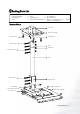
Packing Parts List U-PLATE CEILING ADAPTER M4 SCREWS x 4 TUBE NUTS x 4 PIPE SQUARE TUBE ADJUSTMENT ASSEMBLY PROJECTOR ADAPTER M3 SCREWS x 8 M6 SCREWS x 4 BOLTS x 7 (TUBE BOLTS x 2, L – ADJUST BOLT x 2, TUBE BOLTS x 2) Names of Parts U - PLATE CEILING ADAPTER M4 SCREWS x 4 M3 SCREWS x 2 TUBE BOLTS x 2 TUBE NUTS x 4 L-ADJUST BOLTS x 2 PIPE TUBE BOLTS x 3 SQUARE TUBE M3 SCREWS x 2 ADJUSTMENT ASSEMBLY M3 SCREWS x 4 M6 SCREWS x 4 PROJECTOR ADAPTER Packing Parts List 3
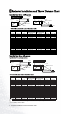
Projector Installation and Throw Distance Chart Installation for a 16:9 screen Ceiling Installation Diagonal Projection Distance Diagonal Floor Installation Ceiling Screen Center of the lens Height Height Offset Center of the lens Offset Screen Projection Distance Floor 16:9 (widescreen) ratio screen dimension table Screen Dimensions (inch / cm) Projection Distance (inch / cm) Diagonal Width Height 50 / 127 60 / 152 70 / 178 80 / 203 90 / 229 100 / 254 110 / 279 120 / 305 130 / 325 140 / 35
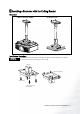
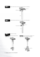
Installing a Projector with the Ceiling Bracket Overview Q Diagram of completed installation Q Ceiling Mount Device Installation Procedure Insert the U-PLATE into the CEILING ADAPTER, and tighten two M4 SCREWS (from the bottom) STEP A into the screw holes. Then attach the top part to the ceiling.
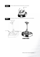
STEP B Install the TUBE and the U-PLATE with 2 sets of BOLTS & NUTS (TUBE BOLT). NUTS x 2 TUBE BOLTS x 2 TUBE STEP C Install the PIPE and the TUBE with 2 sets of BOLTS & NUTS (L-ADJUST BOLT). NUTS x 2 L-ADJUST BOLTS x2 PIPE STEP D Install the base-assembly. STEP D1 Combine the SQUARE TUBE and the PIPE with 2 BOLTS. STEP D2 Install the ADJUSTMENT ASSEMBLY to the SQUARE TUBE with one BOLT and 2 M3 SCREWS.
STEP E Assemble the PROJECTOR ADAPTER and PROJECTOR with 4 M6 SCREWS. M6 SCREW STEP F Slide the projector with adapter into the ceiling assembly and fix the projector with 4 M3 SCREWS. Ceiling mount bracket BASE-ASSEMBLY M3 SCREW Installation finished.
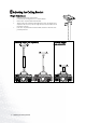
Adjusting the Ceiling Bracket Height Adjustment 1. 2. 3. 4. 5. Make sure to remove the projector first. Loosen the nuts securing to the two L-ADJUST BOLTS. Remove the L-ADJUST BOLTS from the PIPE. Adjust to the correct position for the height of the screen. The height can be adjusted to 309 mm or any value in a range between 639 mm and 849 mm in increments of 30 mm. Insert the L-ADJUST BOLT back into the PIPE, and then re-attach the nuts previously removed.
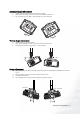
Horizontal Angle Adjustment 1. 2. 3. Hold the projector’s right and left sides and push it up slightly. Adjust the horizontal angle so that it is correct for the orientation of the screen. The swivel angle can be set within a range of negative to positive 30 degrees. 30 Vertical Angle Adjustment 1. 2. 3. Hold the projector’s right and left sides. Adjust the vertical angle so that it is correct for the orientation of the screen. The tilt angle can be set in a range between –5 and +30 degrees.
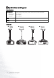
Specifications and Diagrams Specifications Adjustment Range Height Horizontal angle Vertical angle Swing angle 309 mm, 639 mm, 669 mm, 699 mm, 729 mm, 759 mm, 789 mm, 819 mm and 849 mm. –30 to +30 degrees -5 to +30 degrees -15 to +15 degrees Weight 4.2 kg Loading 4.