
User Manual
SJ-PM-TFmini-T-01 A03
Benewake (Beijing) Co. Ltd.
Page16
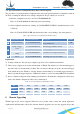
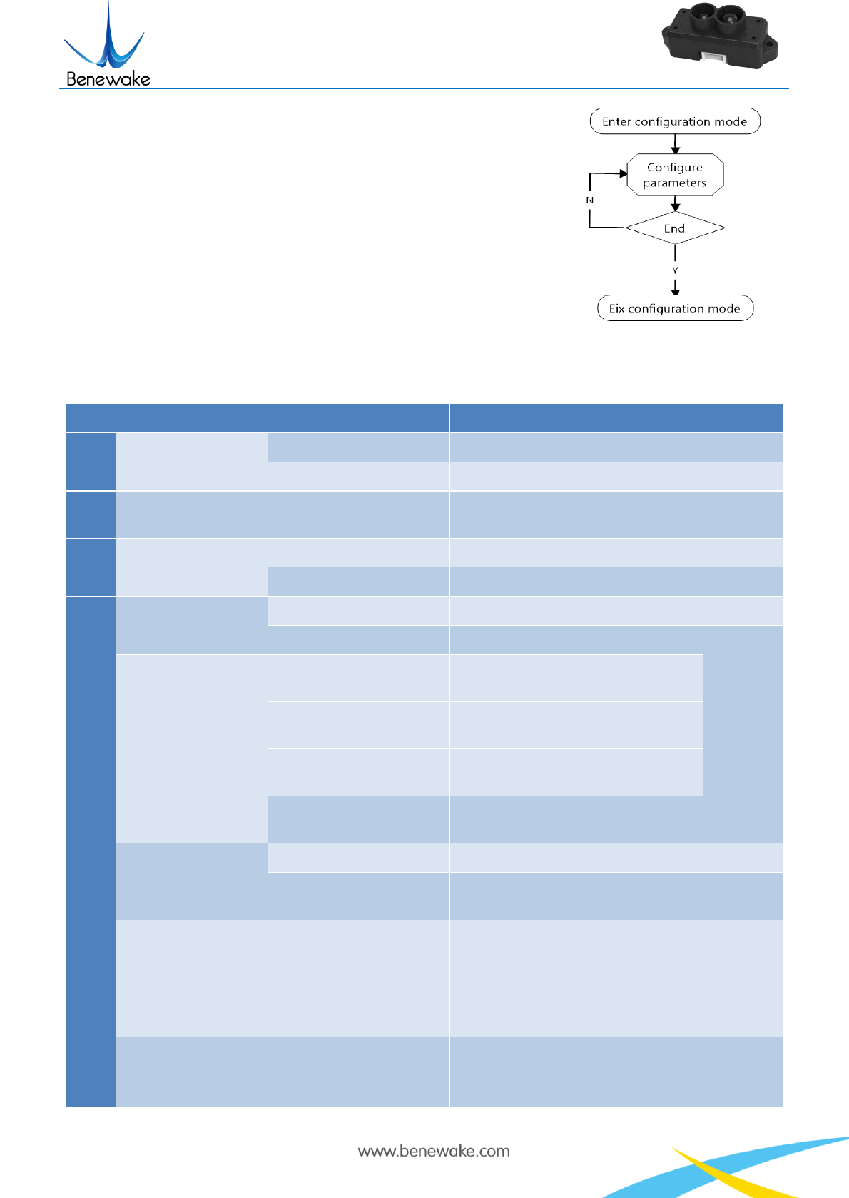
a) Enter configuration mode by the command: 42 57 02 00 00 00
01 02
Echo: 42 57 02 01 00 00 01 02, indicating successful sending;
b) Configure product parameters by the command: 42 57 02 00
EE FF GG HH (Table 8)
Echo: 42 57 02 01 00 00 01 02, indicating successful sending;
c) Exit configuration mode by the command: 42 57 02 00 00 00
00 02
Echo: 42 57 02 01 00 00 00 02, indicating the successful input
of the command;
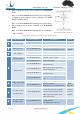
Table 8 General Parameter Configuration and Description
S.N.
Configurable items
List of commands
Description
Default
①
Output data format
42 57 02 00 00 00 01 06
Standard format, as show in in Table 6
√
42 57 02 00 00 00 04 06
“Pixhawk” data format
/
②
Data output cycle
42 57 02 00 EE FF 00 07
EE FF: setting of output cycle (ms)
it must be the integral multiple of 10ms
10ms/
100Hz
③
Unit of distance
42 57 02 00 00 00 00 1A
Output unit of distance data is mm
/
42 57 02 00 00 00 01 1A
Output unit of distance data is cm
√
④
Detection pattern
42 57 02 00 00 00 00 14
Automatic detection pattern
√
42 57 02 00 00 00 01 14
Fix detection pattern
/
Distance mode
42 57 02 00 00 00 00 11
Short distance mode, applicable for 0-
2m(16X firmware)
42 57 02 00 00 00 03 11
Middle distance mode, applicable for
0.5-5m(16X firmware)
42 57 02 00 00 00 02 11
Short distance mode, applicable for 0-
5m(15X firmware)
42 57 02 00 00 00 07 11
Long distance mode, applicable for 1-
12m
⑤
Setting of range limit
42 57 02 00 00 00 00 19
Range limit disabled
/
42 57 02 00 EE FF 01 19
Range limit enabled
EE FF: threshold of ranging limit (mm)
Range
limit: 12m
⑥
lower limit of signal
strength threshold
42 57 02 00 EE 00 00 20
EE: setting of the lower limit of signal
strength threshold. If the real signal is
lower than the set threshold, “FF FF”
will be output as the distance value
which means invalid.
minimum
threshold
20(DEC)
⑦
upper limit of signal
strength threshold
42 57 02 00 EE FF GG 21
EE FF: setting of the maximum signal
strength threshold
GG: output distance value (cm)
/
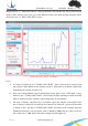
Figure 8 Flow Chart of General
Parameter Configuration