
Use and Care Manual
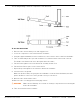
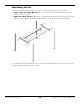
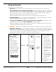
Table Of Contents
- HD-9 Manual
- Table of Contents
- Introduction
- Shipping Information
- Safety Considerations
- Components
- Specifications
- Frequently Asked Questions
- Installation Checklist
- Installation
- Being Safe
- Using Tools
- Planning for Electrical Work
- Selecting a Location
- Checking Clearances
- Deciding the Lift Orientation
- Creating Chalk Line Guides
- Unloading and Unpacking
- Moving the Posts into Position
- Installing the Crosstubes
- About Safety Locks
- Installing the Ladders and Top Cap
- Raising the Crosstubes
- Securing the Ladders
- Removing the Sheaves
- Installing the Runways
- Installing the First End of the Flex Tube
- Routing the Lifting Cables
- Working with Compression Fittings and Tubing
- Installing the Air Lines
- Installing the Return Line
- Hydraulic Fluid Contamination
- About Thread Sealants
- Installing the Hydraulic Hose
- Installing the Power Unit
- Filling the Hydraulic Fluid Reservoir
- Installing the Second End of the Flex Tube
- Installing the Pushbutton Air Valve
- Connecting the Return Line
- Connecting the Hydraulic Hose
- Contacting the Electrician
- Connecting the Power Source
- Installing a Power Disconnect Switch
- Installing a Thermal Disconnect Switch
- About Effective Embedment
- Anchoring the Posts
- Final Leveling
- Installing Accessories
- Lubricating the Lift
- Bleeding the Hydraulic Cylinder
- Test the Lift
- Final Checklist
- Outdoor usage
- Operation
- Maintenance
- Troubleshooting
- Wiring Diagrams
- Labels
- Parts Drawings
- Automotive Lift Institute (ALI) Store

HD-9 Series Four-Post Lifts 69 P/N 5900123 — Rev. M1 — March 2020
Using the Controls
The Controls for your Lift include:
• Up button. Press and hold to raise the Runways. Located near the top of the Power Unit.
To put Runways onto a Safety Lock position
: Raise the Runways a little above where you
want them, then press and hold the Lowering Handle to back the Runways down onto the Safety
Locks position (do not press and hold the pushbutton on the Pushbutton Air Valve). When the
Runways stop going down, they are engaged on a Safety Lock.
Before leaving the Lift, make sure all four corners are engaged on their Safety Locks.
• Lowering Handle. Press and hold to lower the Runways. Located in the middle of the Power
Unit, the Lowering Handle is long and has a ball at the end.
To lower raised Runways down to the ground
:
press and hold
the Pushbutton on the
Pushbutton Air Valve first, then
press and hold
the Lowering Handle.
Watch the Runways as they go down to make sure they are coming down evenly. If they are not,
stop lowering the Lift and troubleshoot the problem.
⚠ WARNING Only leave the Runways either engaged on a Safety Lock position or fully lowered.
• Pushbutton Air Valve. Press and hold the Pushbutton on the Pushbutton Air Valve as part of
the process to lower the Runways. Located on one side or the other of the Power Unit (depending
on where it was installed). Pressing and holding the Pushbutton on the Pushbutton Air Valve
disengages the Safety Locks, which is needed to lower the Runways.
To raise Runways to
a Safety Lock:
1. Press and hold Up
Button.
2. When just past
desired height,
release Up Button.
3. Press and hold
Lowering Handle.
4. Runways stop going
down when engaged
on a Safety Lock;
release Lowering
Handle when they
stop.
Do not press and
hold Pushbutton.
To lower Runways:
1. Press the Up
Button for a
second or two.
This disengages
the Runways from
the Safety Locks.
2. Press and hold
Pushbutton and
Lowering Handle
at the same time.
Runways begin
lowering.
3. When Runways
are fully lowered,
release Pushbutton
and Lowering
Handle.
4. Drive Vehicle off
Runways.