
Use and Care Manual
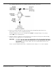
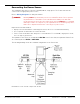
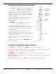
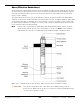


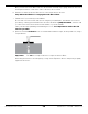
Table Of Contents
- HD-9 Manual
- Table of Contents
- Introduction
- Shipping Information
- Safety Considerations
- Components
- Specifications
- Frequently Asked Questions
- Installation Checklist
- Installation
- Being Safe
- Using Tools
- Planning for Electrical Work
- Selecting a Location
- Checking Clearances
- Deciding the Lift Orientation
- Creating Chalk Line Guides
- Unloading and Unpacking
- Moving the Posts into Position
- Installing the Crosstubes
- About Safety Locks
- Installing the Ladders and Top Cap
- Raising the Crosstubes
- Securing the Ladders
- Removing the Sheaves
- Installing the Runways
- Installing the First End of the Flex Tube
- Routing the Lifting Cables
- Working with Compression Fittings and Tubing
- Installing the Air Lines
- Installing the Return Line
- Hydraulic Fluid Contamination
- About Thread Sealants
- Installing the Hydraulic Hose
- Installing the Power Unit
- Filling the Hydraulic Fluid Reservoir
- Installing the Second End of the Flex Tube
- Installing the Pushbutton Air Valve
- Connecting the Return Line
- Connecting the Hydraulic Hose
- Contacting the Electrician
- Connecting the Power Source
- Installing a Power Disconnect Switch
- Installing a Thermal Disconnect Switch
- About Effective Embedment
- Anchoring the Posts
- Final Leveling
- Installing Accessories
- Lubricating the Lift
- Bleeding the Hydraulic Cylinder
- Test the Lift
- Final Checklist
- Outdoor usage
- Operation
- Maintenance
- Troubleshooting
- Wiring Diagrams
- Labels
- Parts Drawings
- Automotive Lift Institute (ALI) Store

HD-9 Series Four-Post Lifts 52 P/N 5900123 — Rev. M1 — March 2020
Connecting the Return Line
The Return Line should already be routed through the Flex Tube and connected to the Return Line
connector on the Hydraulic Cylinder; the other end of the Return Line needs to be connected to the
Power Unit.
To attach the Return Line to the Power Unit:
1. Find an Elbow Compression Fitting (04 COMP – 06 NPT) from the Parts Bag.
2. Locate the Hydraulic Return connector on the Power Unit and remove the Shipping Plug.
See Connecting the Power Source for the possible connector locations.
3. Connect and tighten the threaded end of the Elbow Compression Fitting to the Hydraulic Return
connector on the Power Unit.
For information about connection compression fittings, refer to Working with Compression
Fittings and Tubing.
4. Find the Return Line coming out of the Flex Tube and connect it to the other connector on the
Elbow Compression Fitting.
Important: The Air Line, at one point, was also coming out of the Flex Tube and it uses the
same kind of tubing as the Return Line. The Air Line should have been connected in
the previous section, but if it was not, make sure you are attaching the Return Line
to the Power Unit and not the Air Line.
Do not attach the Air Line to the
Power Unit by mistake
.
Connecting the Hydraulic Hose
The Hydraulic Hose connects to a Hydraulic Power Out connector on the Power Unit; the Curved end
of the Hydraulic Hose is already connected to the Hydraulic Cylinder, the other end should be coming
out of the Flex Tube.
To connect the Hydraulic Hose:
1. Find the Hydraulic Fitting (04 JIC – 06 ORB). The Hydraulic Hose is already in place, with the
Straight end coming out of the Flex Tube.
2. Locate the Hydraulic Power Out connector on the Power Unit you want to use and remove the
Shipping Plug.
See Connecting the Power Source for the possible connector locations.
3. Connect and securely tighten the ORB end of the JIC – ORB Fitting to the Hydraulic Power Out on
the Power Unit.
4. Connect and securely tighten the JIC end of the JIC – ORB Fitting to the Hydraulic Hose coming
out of the Flex Tube.