
Use and Care Manual
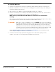
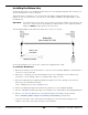
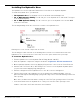
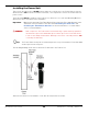
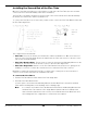
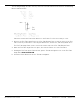
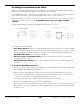
Table Of Contents
- HD-9 Manual
- Table of Contents
- Introduction
- Shipping Information
- Safety Considerations
- Components
- Specifications
- Frequently Asked Questions
- Installation Checklist
- Installation
- Being Safe
- Using Tools
- Planning for Electrical Work
- Selecting a Location
- Checking Clearances
- Deciding the Lift Orientation
- Creating Chalk Line Guides
- Unloading and Unpacking
- Moving the Posts into Position
- Installing the Crosstubes
- About Safety Locks
- Installing the Ladders and Top Cap
- Raising the Crosstubes
- Securing the Ladders
- Removing the Sheaves
- Installing the Runways
- Installing the First End of the Flex Tube
- Routing the Lifting Cables
- Working with Compression Fittings and Tubing
- Installing the Air Lines
- Installing the Return Line
- Hydraulic Fluid Contamination
- About Thread Sealants
- Installing the Hydraulic Hose
- Installing the Power Unit
- Filling the Hydraulic Fluid Reservoir
- Installing the Second End of the Flex Tube
- Installing the Pushbutton Air Valve
- Connecting the Return Line
- Connecting the Hydraulic Hose
- Contacting the Electrician
- Connecting the Power Source
- Installing a Power Disconnect Switch
- Installing a Thermal Disconnect Switch
- About Effective Embedment
- Anchoring the Posts
- Final Leveling
- Installing Accessories
- Lubricating the Lift
- Bleeding the Hydraulic Cylinder
- Test the Lift
- Final Checklist
- Outdoor usage
- Operation
- Maintenance
- Troubleshooting
- Wiring Diagrams
- Labels
- Parts Drawings
- Automotive Lift Institute (ALI) Store

HD-9 Series Four-Post Lifts 49 P/N 5900123 — Rev. M1 — March 2020
The following drawing describes how to position the Flex Tube Bracket Plate between the Mounting
Bracket and Back Plate.
Side view of where the Power Unit attaches to the Power Post. Not necessarily to scale.
3. Connect the Flex Tube Angle Plate to the Flex Tube Bracket Plate so that the holes for the Flex
Tubes are best positioned for connecting the Return Line, the Air Line, and the Hydraulic Hose.
The Flex Tube Angle Plate can be connected on either side of the Flex Tube Bracket Plate.
4. When the Flex Tube Angle Plate is in place, unscrew the Plastic one of the Flex Tubes.
5. Holding the Flex Tube by the Plastic Collar, put the Threads through the hole on the Flex Tube
Angle Plate
from underneath
.
6. Screw the Plastic Nut back onto the Threads and tighten.