
Use and Care Manual
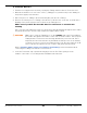
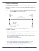
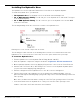
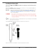
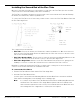
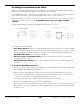
Table Of Contents
- HD-9 Manual
- Table of Contents
- Introduction
- Shipping Information
- Safety Considerations
- Components
- Specifications
- Frequently Asked Questions
- Installation Checklist
- Installation
- Being Safe
- Using Tools
- Planning for Electrical Work
- Selecting a Location
- Checking Clearances
- Deciding the Lift Orientation
- Creating Chalk Line Guides
- Unloading and Unpacking
- Moving the Posts into Position
- Installing the Crosstubes
- About Safety Locks
- Installing the Ladders and Top Cap
- Raising the Crosstubes
- Securing the Ladders
- Removing the Sheaves
- Installing the Runways
- Installing the First End of the Flex Tube
- Routing the Lifting Cables
- Working with Compression Fittings and Tubing
- Installing the Air Lines
- Installing the Return Line
- Hydraulic Fluid Contamination
- About Thread Sealants
- Installing the Hydraulic Hose
- Installing the Power Unit
- Filling the Hydraulic Fluid Reservoir
- Installing the Second End of the Flex Tube
- Installing the Pushbutton Air Valve
- Connecting the Return Line
- Connecting the Hydraulic Hose
- Contacting the Electrician
- Connecting the Power Source
- Installing a Power Disconnect Switch
- Installing a Thermal Disconnect Switch
- About Effective Embedment
- Anchoring the Posts
- Final Leveling
- Installing Accessories
- Lubricating the Lift
- Bleeding the Hydraulic Cylinder
- Test the Lift
- Final Checklist
- Outdoor usage
- Operation
- Maintenance
- Troubleshooting
- Wiring Diagrams
- Labels
- Parts Drawings
- Automotive Lift Institute (ALI) Store

HD-9 Series Four-Post Lifts 48 P/N 5900123 — Rev. M1 — March 2020
Installing the Second End of the Flex Tube
Once the Power Unit is installed, you can install the second end of the Flex Tube (the other end was
connected to the Powerside Runway earlier in the installation).
The Flex Tube consolidates and protects the lines that come out from under the Powerside Runway:
the Air Line, the Return Line, and the Hydraulic Hose.
To connect the Flex Tube to the Power Unit, you first need to connect the Flex Tube Bracket Plate and
the Flex Tube Angle Plate.
The components involved include:
• Flex Tube. Protects the Air Line, the Return Line, and the Hydraulic Hose. One end connects to
the hole on the Flex Tube Angle Plate from underneath, the other end connects to the hole on the
side of the Powerside Runway.
• Flex Tube Bracket Plate. The two notches at the top attach near the Mounting Bracket on the
Power Post. The two holes at the bottom connect to the Flex Tube Angle Plate.
• Flex Tube Angle Plate. Attaches to the Flex Tube Bracket Plate via two holes, giving you the
flexibility to connect it on either side. Includes the hole to which the Flex Tube connects.
BendPak recommends orienting the Flex Tube so that the lines coming out of it are near where it
connects on the Power Unit and to the Pushbutton Air Valve.
To connect the Flex Tubes:
1. Find the Flex Tube Bracket Plate and the Flex Tube Angle Plate.
2. Install the Flex Tube Bracket Plate.
Location options are: between the Mounting Bracket and the Back Plate or between the Back
Plate and the retaining Nut (see the drawing on the following page).
Note: It is common to install the Flex Tube Bracket Plate between the Mounting Bracket and
the Back Plate. This allows the Zero Angle Bracket (which holds the Pushbutton Air
Valve and is described in the next section) to be installed between the Back Plate and
the retaining Nut. This configuration is common, but not required.