
Use and Care Manual
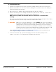
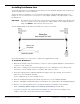
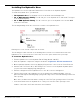
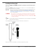
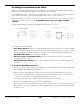
Table Of Contents
- HD-9 Manual
- Table of Contents
- Introduction
- Shipping Information
- Safety Considerations
- Components
- Specifications
- Frequently Asked Questions
- Installation Checklist
- Installation
- Being Safe
- Using Tools
- Planning for Electrical Work
- Selecting a Location
- Checking Clearances
- Deciding the Lift Orientation
- Creating Chalk Line Guides
- Unloading and Unpacking
- Moving the Posts into Position
- Installing the Crosstubes
- About Safety Locks
- Installing the Ladders and Top Cap
- Raising the Crosstubes
- Securing the Ladders
- Removing the Sheaves
- Installing the Runways
- Installing the First End of the Flex Tube
- Routing the Lifting Cables
- Working with Compression Fittings and Tubing
- Installing the Air Lines
- Installing the Return Line
- Hydraulic Fluid Contamination
- About Thread Sealants
- Installing the Hydraulic Hose
- Installing the Power Unit
- Filling the Hydraulic Fluid Reservoir
- Installing the Second End of the Flex Tube
- Installing the Pushbutton Air Valve
- Connecting the Return Line
- Connecting the Hydraulic Hose
- Contacting the Electrician
- Connecting the Power Source
- Installing a Power Disconnect Switch
- Installing a Thermal Disconnect Switch
- About Effective Embedment
- Anchoring the Posts
- Final Leveling
- Installing Accessories
- Lubricating the Lift
- Bleeding the Hydraulic Cylinder
- Test the Lift
- Final Checklist
- Outdoor usage
- Operation
- Maintenance
- Troubleshooting
- Wiring Diagrams
- Labels
- Parts Drawings
- Automotive Lift Institute (ALI) Store

HD-9 Series Four-Post Lifts 42 P/N 5900123 — Rev. M1 — March 2020
Installing the Return Line
The Return Line takes excess Hydraulic Fluid coming out of the Hydraulic Cylinder and sends it back
into the Fluid Reservoir on the Power Unit.
The Return Line is a single piece of ¼ inch, black, polyethylene Tubing with Elbow Compression
Fittings on each end. You need to cut off a piece of the supplied Tubing of the right length to create
the Return Line.
Important: The Return Line uses the same ¼ inch, black, polyethylene Tubing as the Air Lines. Be
sure not to confuse the two; the Return Line and the Air Lines do completely different
things and
must
be kept separate from each other.
The following drawing shows where the Return Line connects on the Lift.
Front view. Drawing not to scale. Some components exaggerated for clarity.
To install the Return Line:
1. Measure the distance from the Return Line connector on the Hydraulic Cylinder to the Return Line
connector on the Power Unit.
2. Cut a piece of Tubing to the measured length from the roll of Tubing that comes with the Lift.
It is better to cut the Tubing a little too long rather than a little too short.
3. Route the Tubing from the Hydraulic Cylinder through the Flex Tube opening, and out next to
where the Power Unit will be installed.
Let the Tubing hang out of the opening for now.
4. Remove the Shipping Plug from the Return Line Connector on the Hydraulic Cylinder.
5. Connect and tighten the Elbow Compression Fitting into the opening where the Shipping Plug was.
6. Connect one end of the Return Line to the Elbow Compression Fitting you just installed.
Refer to Working with Compression Fittings and Tubing for instructions.
7. Leave the Power Unit end of the Return Line hanging out of the Flex Tube opening for now.
It will be connected to the Power Unit later in the installation.