
Use and Care Manual
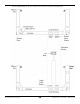
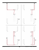
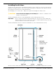
Table Of Contents
- HD-9 Manual
- Table of Contents
- Introduction
- Shipping Information
- Safety Considerations
- Components
- Specifications
- Frequently Asked Questions
- Installation Checklist
- Installation
- Being Safe
- Using Tools
- Planning for Electrical Work
- Selecting a Location
- Checking Clearances
- Deciding the Lift Orientation
- Creating Chalk Line Guides
- Unloading and Unpacking
- Moving the Posts into Position
- Installing the Crosstubes
- About Safety Locks
- Installing the Ladders and Top Cap
- Raising the Crosstubes
- Securing the Ladders
- Removing the Sheaves
- Installing the Runways
- Installing the First End of the Flex Tube
- Routing the Lifting Cables
- Working with Compression Fittings and Tubing
- Installing the Air Lines
- Installing the Return Line
- Hydraulic Fluid Contamination
- About Thread Sealants
- Installing the Hydraulic Hose
- Installing the Power Unit
- Filling the Hydraulic Fluid Reservoir
- Installing the Second End of the Flex Tube
- Installing the Pushbutton Air Valve
- Connecting the Return Line
- Connecting the Hydraulic Hose
- Contacting the Electrician
- Connecting the Power Source
- Installing a Power Disconnect Switch
- Installing a Thermal Disconnect Switch
- About Effective Embedment
- Anchoring the Posts
- Final Leveling
- Installing Accessories
- Lubricating the Lift
- Bleeding the Hydraulic Cylinder
- Test the Lift
- Final Checklist
- Outdoor usage
- Operation
- Maintenance
- Troubleshooting
- Wiring Diagrams
- Labels
- Parts Drawings
- Automotive Lift Institute (ALI) Store

HD-9 Series Four-Post Lifts 40 P/N 5900123 — Rev. M1 — March 2020
Installing the Air Lines
The Air Lines use air pressure to disengage the Safety Locks in each Post so that you can lower the
Runways. You will need more of the ¼ inch, black, polyethylene Tubing that came with the Lift and
three Air Line Tee Connectors to install the Air Lines.
An Air Supply (3 to 25 cfm at 50 — 150 psi) is required to disengage the Safety Locks.
⚠ CAUTION
Do not let the Air Supply exceed 150 psi
; the Air Lines could burst or the
Safety Locks malfunction.
The Air Line Elbow Connectors on the Air Cylinders come installed from the factory.
Important: Do not confuse the Air Lines with the Return Line. They use the same Tubing and
similar-looking connectors, but they are used for completely different things; the two
systems cannot be connected to each other.
The Air Line Elbow Connectors on the Crosstube Gussets come installed from the factory.
Air Lines shown outside Steel Tubes for clarity. Drawing not to scale. Some components not shown.