
Use and Care Manual
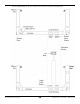
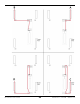
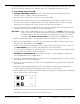
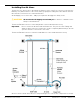
Table Of Contents
- HD-9 Manual
- Table of Contents
- Introduction
- Shipping Information
- Safety Considerations
- Components
- Specifications
- Frequently Asked Questions
- Installation Checklist
- Installation
- Being Safe
- Using Tools
- Planning for Electrical Work
- Selecting a Location
- Checking Clearances
- Deciding the Lift Orientation
- Creating Chalk Line Guides
- Unloading and Unpacking
- Moving the Posts into Position
- Installing the Crosstubes
- About Safety Locks
- Installing the Ladders and Top Cap
- Raising the Crosstubes
- Securing the Ladders
- Removing the Sheaves
- Installing the Runways
- Installing the First End of the Flex Tube
- Routing the Lifting Cables
- Working with Compression Fittings and Tubing
- Installing the Air Lines
- Installing the Return Line
- Hydraulic Fluid Contamination
- About Thread Sealants
- Installing the Hydraulic Hose
- Installing the Power Unit
- Filling the Hydraulic Fluid Reservoir
- Installing the Second End of the Flex Tube
- Installing the Pushbutton Air Valve
- Connecting the Return Line
- Connecting the Hydraulic Hose
- Contacting the Electrician
- Connecting the Power Source
- Installing a Power Disconnect Switch
- Installing a Thermal Disconnect Switch
- About Effective Embedment
- Anchoring the Posts
- Final Leveling
- Installing Accessories
- Lubricating the Lift
- Bleeding the Hydraulic Cylinder
- Test the Lift
- Final Checklist
- Outdoor usage
- Operation
- Maintenance
- Troubleshooting
- Wiring Diagrams
- Labels
- Parts Drawings
- Automotive Lift Institute (ALI) Store

HD-9 Series Four-Post Lifts 37 P/N 5900123 — Rev. M1 — March 2020
5. With the Lifting Cable in place, reinstall the Gusset Sheave and the Cable Lock Pin in Post A.
6. Make sure Lifting Cable A is correctly positioned: in between the Gusset Sheave and the Slack
Safety Sheave, with the Cable Lock Pin
under
it.
7. Push the Threaded End of Lifting Cable A up to and through the Top Cap (at the top of the Post)
and
hand tighten
it in place with the Nut and Washer you removed earlier.
You only want to hand tighten the Nut at this point so that there is little play in the cabling. We will
securely tighten all four Nuts later in the installation procedure.
8.
Switching to Lifting Cable C
, repeat Steps 1 through 7 for Lifting Cable C, starting at the
Small Window near the bottom of Post C (the Power Post).
9. Reinstall a Single Cable Sheave and then make sure Lifting Cable C is correctly positioned in the
Cable Sheave in the Small Window.
10. Under the Powerside Runway, move the rest of Lifting Cable C back towards the Crosstube with
Large Windows.
11. Reinstall the Double Cable Sheave in place in the Large Window, making sure Lifting Cable A is
seated in the Bottom Sheave and Lifting Cable C is seated in the Top Sheave, as shown below.
The following drawing shows the Cable/Cable Sheave pairs in the Crosstube with Large Windows.
Front view. Double Cable Sheaves separated for easier understanding. Not all components shown.
Not necessarily to scale.
12. By the Hydraulic Cylinder, loosen the Retaining Plate enough to give you room to slip the Button
End of each Cable into its spot on the Tie Plate.
Do not take the Retaining Plate off
, just loosen the Retaining Plate enough to give you
enough room to slip the Button End of each Lifting Cable into place.
13. Pull the Button Ends of Lifting Cables A and C back towards the middle of the Runway, past the
Retaining Plate, and into its slot on the Tie Plate.
Drawing shows a front view of the Tie Plate, facing towards the Crosstube with Large Windows.
Lifting Cables A and C are now correctly routed to their Posts.