
Use and Care Manual
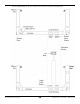
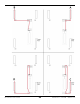
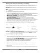
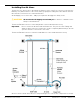
Table Of Contents
- HD-9 Manual
- Table of Contents
- Introduction
- Shipping Information
- Safety Considerations
- Components
- Specifications
- Frequently Asked Questions
- Installation Checklist
- Installation
- Being Safe
- Using Tools
- Planning for Electrical Work
- Selecting a Location
- Checking Clearances
- Deciding the Lift Orientation
- Creating Chalk Line Guides
- Unloading and Unpacking
- Moving the Posts into Position
- Installing the Crosstubes
- About Safety Locks
- Installing the Ladders and Top Cap
- Raising the Crosstubes
- Securing the Ladders
- Removing the Sheaves
- Installing the Runways
- Installing the First End of the Flex Tube
- Routing the Lifting Cables
- Working with Compression Fittings and Tubing
- Installing the Air Lines
- Installing the Return Line
- Hydraulic Fluid Contamination
- About Thread Sealants
- Installing the Hydraulic Hose
- Installing the Power Unit
- Filling the Hydraulic Fluid Reservoir
- Installing the Second End of the Flex Tube
- Installing the Pushbutton Air Valve
- Connecting the Return Line
- Connecting the Hydraulic Hose
- Contacting the Electrician
- Connecting the Power Source
- Installing a Power Disconnect Switch
- Installing a Thermal Disconnect Switch
- About Effective Embedment
- Anchoring the Posts
- Final Leveling
- Installing Accessories
- Lubricating the Lift
- Bleeding the Hydraulic Cylinder
- Test the Lift
- Final Checklist
- Outdoor usage
- Operation
- Maintenance
- Troubleshooting
- Wiring Diagrams
- Labels
- Parts Drawings
- Automotive Lift Institute (ALI) Store

HD-9 Series Four-Post Lifts 33 P/N 5900123 — Rev. M1 — March 2020
• In the following drawings, the Cables and Cable Sheaves are labeled A, B, C, and D. These letters
are
not
on the label on the Threaded end. You have to match the Cable letter with the length.
• The four Lifting Cables for the HD-9ST are:
o A: 2,926 mm / 9.7 feet / 115.25 inches
o B: 4,356 mm / 14.4 feet / 171.5 inches
o C: 7,048 mm / 23.2 feet / 277.5 inches
o D: 8,476 mm / 27.10 feet / 333.75 inches
• The four Lifting Cables for the HD-9STX are:
o A: 3,240 mm / 11 feet / 127.5 inches
o B: 4,663 mm / 15 feet / 183.5 inches
o C: 7,978 mm / 26 feet / 314 inches
o D: 9,404 mm / 30 feet / 370.25 inches
• The four Lifting Cables for the HD-9 are:
o A: 2,958 mm / 9.9 feet / 116.5 inches
o B: 4,578 mm / 15 feet / 180.25 inches
o C: 7,094 mm / 23.4 feet / 279.25 inches
o D: 8,706 mm / 28.7 feet / 342.75 inches
• The four Lifting Cables for the HD-9XL are:
o A: 3,582 mm / 11.9 feet / 141 inches
o B: 5,195 mm / 17 feet / 204.5 inches
o C: 8,332 mm / 27.4 feet / 328 inches
o D: 9,932 mm / 32.7 feet / 391 inches
• The four Lifting Cables for the HD-9XW are:
o A: 3,263 mm / 10.8 feet / 128.5 inches
o B: 4,883 mm / 16 feet / 192.25 inches
o C: 8,007 mm / 26.3 feet / 315.25 inches
o D: 9,613 mm / 31.7 feet / 378.5 inches
Important: Make sure to use the correct Lifting Cable for each routing. If you put a Cable in the
wrong place, it will be too short or too long. Remember that the length of each Cable
is printed on the label on the Threaded end.
• Lifting Cables A and B pass around one Cable Sheave and one Gusset Sheave. Lifting Cables C
and D pass around two Cable Sheaves and one Gusset Sheave.
See the drawing on the following page for routing information.