
Use and Care Manual
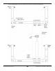
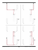
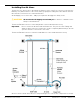
Table Of Contents
- HD-9 Manual
- Table of Contents
- Introduction
- Shipping Information
- Safety Considerations
- Components
- Specifications
- Frequently Asked Questions
- Installation Checklist
- Installation
- Being Safe
- Using Tools
- Planning for Electrical Work
- Selecting a Location
- Checking Clearances
- Deciding the Lift Orientation
- Creating Chalk Line Guides
- Unloading and Unpacking
- Moving the Posts into Position
- Installing the Crosstubes
- About Safety Locks
- Installing the Ladders and Top Cap
- Raising the Crosstubes
- Securing the Ladders
- Removing the Sheaves
- Installing the Runways
- Installing the First End of the Flex Tube
- Routing the Lifting Cables
- Working with Compression Fittings and Tubing
- Installing the Air Lines
- Installing the Return Line
- Hydraulic Fluid Contamination
- About Thread Sealants
- Installing the Hydraulic Hose
- Installing the Power Unit
- Filling the Hydraulic Fluid Reservoir
- Installing the Second End of the Flex Tube
- Installing the Pushbutton Air Valve
- Connecting the Return Line
- Connecting the Hydraulic Hose
- Contacting the Electrician
- Connecting the Power Source
- Installing a Power Disconnect Switch
- Installing a Thermal Disconnect Switch
- About Effective Embedment
- Anchoring the Posts
- Final Leveling
- Installing Accessories
- Lubricating the Lift
- Bleeding the Hydraulic Cylinder
- Test the Lift
- Final Checklist
- Outdoor usage
- Operation
- Maintenance
- Troubleshooting
- Wiring Diagrams
- Labels
- Parts Drawings
- Automotive Lift Institute (ALI) Store

HD-9 Series Four-Post Lifts 32 P/N 5900123 — Rev. M1 — March 2020
Routing the Lifting Cables
Before routing the Lifting Cables on your Lift, you need to know the following:
• BendPak strongly recommends using protective gloves when working with the Lifting Cables.
• Each Lift has four Lifting Cables of varying lengths and can only make one connection.
• All Lifting Cables have a Button End and a Threaded End. The Threaded End has a label on it that
identifies the Lift model the Cable is designed for (and
must
be used with), the part number (if you
need to replace it), and its length (in millimeters).
• The Button End of each Lifting Cable connects at the Tie Plate on the underside of the Powerside
Runway. The Button Ends of each Lifting Cable stay on one side of the Tie Plate (as shown above),
while the rest of the Cable goes through the Tie Plate and the Retaining Plate on its way towards
the appropriate Sheaves and then to the Posts to which it attaches.
• The Threaded End of each Lifting Cable goes around the appropriate Sheaves and then gets
routed to a Post, where it is attached at the top.
• Before routing each Lifting Cable, remove the Nut at the Threaded End; you cannot route the
Lifting Cable around the Sheaves if the Nut is still on.
• The Lift comes with a Retaining Plate on one side of the Tie Plate. The Retaining Plate holds the
Button Ends of the Lifting Cable in place after all four Cables are installed.
Do not take the
Retaining Plate off to install the Lifting Cables
; instead, loosen it so that you can slip the
Button End of the Cable into the correct slot. When all four Lifting Cables are installed, tighten the
Retaining Plate.
• There are two kinds of Sheaves: Cable Sheaves and Gusset Sheaves. There are four Cable
Sheaves (two Double Cable Sheaves) in the Crosstube with Large Windows and two Single Cable
Sheaves in the Crosstube with Small Windows, for a total of six Cable Sheaves. There are four
Gusset Sheaves, one per Crosstube Gusset.
• All Sheaves come installed. They should have been removed earlier in the installation prior to
installing the Runways.
• A Lifting Cable and its corresponding Cable Sheave (or Sheaves) are put into place one at a time,
starting from the top of the Post to the Tie Plate.
• The Crosstube with Large Windows has two Double Cable Sheaves (also called twin Cable
Sheaves), so the two Lifting Cables that share a Double Cable Sheave are routed around the same
time; for example, Lifting Cables A and C are routed around the same time because they share a
Double Cable Sheave, and same for Cables B and D.
• Each Crosstube Gusset has a Cable Lock Pin underneath the Gusset Sheave. Each Cable Lock
Pin needs to be removed when routing the Cable to its Post and then reinstalled once the Cable is
in place.
• The Cable Lock Pin prevents the Cable from coming out later; there is not enough space between
the bottom of the Gusset Sheave and the Cable Lock Pin for the Cable to slip out.