
Use and Care Manual
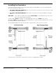
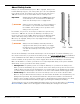
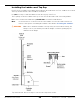
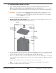

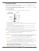
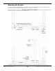
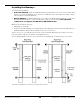
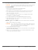
Table Of Contents
- HD-9 Manual
- Table of Contents
- Introduction
- Shipping Information
- Safety Considerations
- Components
- Specifications
- Frequently Asked Questions
- Installation Checklist
- Installation
- Being Safe
- Using Tools
- Planning for Electrical Work
- Selecting a Location
- Checking Clearances
- Deciding the Lift Orientation
- Creating Chalk Line Guides
- Unloading and Unpacking
- Moving the Posts into Position
- Installing the Crosstubes
- About Safety Locks
- Installing the Ladders and Top Cap
- Raising the Crosstubes
- Securing the Ladders
- Removing the Sheaves
- Installing the Runways
- Installing the First End of the Flex Tube
- Routing the Lifting Cables
- Working with Compression Fittings and Tubing
- Installing the Air Lines
- Installing the Return Line
- Hydraulic Fluid Contamination
- About Thread Sealants
- Installing the Hydraulic Hose
- Installing the Power Unit
- Filling the Hydraulic Fluid Reservoir
- Installing the Second End of the Flex Tube
- Installing the Pushbutton Air Valve
- Connecting the Return Line
- Connecting the Hydraulic Hose
- Contacting the Electrician
- Connecting the Power Source
- Installing a Power Disconnect Switch
- Installing a Thermal Disconnect Switch
- About Effective Embedment
- Anchoring the Posts
- Final Leveling
- Installing Accessories
- Lubricating the Lift
- Bleeding the Hydraulic Cylinder
- Test the Lift
- Final Checklist
- Outdoor usage
- Operation
- Maintenance
- Troubleshooting
- Wiring Diagrams
- Labels
- Parts Drawings
- Automotive Lift Institute (ALI) Store

HD-9 Series Four-Post Lifts 29 P/N 5900123 — Rev. M1 — March 2020
Installing the Runways
Your Lift has two Runways:
• Powerside Runway: Holds the Hydraulic Cylinder underneath it. Has a hole on the outside Rear
that lets you route the Hydraulic Hose, Air Lines, and Return Line to the Power Unit. Cable routing
starts under the Powerside Runway.
• Offside Runway: The Offside Runway does not have a Hydraulic Cylinder under it, nor are there
any Lifting Cables under it. It can be installed in the wide or narrow setting;
the adjustable
setting
does not apply to the HD-9ST or HD-9STX models
.
Orient the two Runways this way:
• Utility Rails on the inside
• Find the Powerside Runway by looking under the two Runways (only the Powerside Runway has a
Hydraulic Cylinder underneath it) and put it next to the Power Post.
There is also an ~1.5-inch wide hole in the side of the Powerside Runway at the Power Post for the
Flex Tube (which holds the Air, Return, and Hydraulic Hose).
The following drawing shows the correct orientation of the Runways for both Power Post locations.
Top View. Not drawn to scale. Not all components shown.