
Use and Care Manual
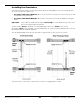
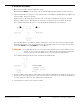
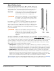
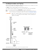
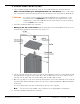

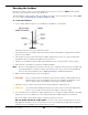
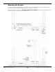
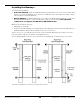
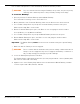
Table Of Contents
- HD-9 Manual
- Table of Contents
- Introduction
- Shipping Information
- Safety Considerations
- Components
- Specifications
- Frequently Asked Questions
- Installation Checklist
- Installation
- Being Safe
- Using Tools
- Planning for Electrical Work
- Selecting a Location
- Checking Clearances
- Deciding the Lift Orientation
- Creating Chalk Line Guides
- Unloading and Unpacking
- Moving the Posts into Position
- Installing the Crosstubes
- About Safety Locks
- Installing the Ladders and Top Cap
- Raising the Crosstubes
- Securing the Ladders
- Removing the Sheaves
- Installing the Runways
- Installing the First End of the Flex Tube
- Routing the Lifting Cables
- Working with Compression Fittings and Tubing
- Installing the Air Lines
- Installing the Return Line
- Hydraulic Fluid Contamination
- About Thread Sealants
- Installing the Hydraulic Hose
- Installing the Power Unit
- Filling the Hydraulic Fluid Reservoir
- Installing the Second End of the Flex Tube
- Installing the Pushbutton Air Valve
- Connecting the Return Line
- Connecting the Hydraulic Hose
- Contacting the Electrician
- Connecting the Power Source
- Installing a Power Disconnect Switch
- Installing a Thermal Disconnect Switch
- About Effective Embedment
- Anchoring the Posts
- Final Leveling
- Installing Accessories
- Lubricating the Lift
- Bleeding the Hydraulic Cylinder
- Test the Lift
- Final Checklist
- Outdoor usage
- Operation
- Maintenance
- Troubleshooting
- Wiring Diagrams
- Labels
- Parts Drawings
- Automotive Lift Institute (ALI) Store

HD-9 Series Four-Post Lifts 22 P/N 5900123 — Rev. M1 — March 2020
To install the Crosstubes:
1. Orient the Crosstubes in their required locations.
Both Windows
must
be on the ends of the Powerside Runway and facing the inside of the Lift.
2. Put black Slide Blocks into place on the outside ends of each Gusset (4 Slide Blocks per Gusset, 8
per Crosstube, 16 total for the Lift).
Align the holes in the Slide Blocks with the rods on the side of the Gusset, then press the Slide
Blocks in. Make sure the Slide Blocks are oriented so that they create a Slot when pushed in.
The following drawing shows how to correctly install two Slide Blocks onto a Gusset.
The four Slide Blocks on a Gusset, when put into place, create two Slots about four inches wide
and half an inch deep. There is one Slot at the top of the Gusset and a second Slot at the bottom;
the Ladder
must
go through
both
Slots on the Gusset.
⚠ WARNING If the Slide Blocks are not correctly installed, then the Slots for the Ladder are not
created. In such a case, the Safety Locks will not work correctly, which endangers
everyone who uses the Lift. Make sure to correctly install the Slide Blocks.
The following drawing shows the Slot created by two Slide Blocks.
3. Using a Forklift or Shop Crane, raise the Crosstube with the Slide Blocks installed above the top of
the two Posts that it goes between, lower it to just over the top of the Post, orient the Slide Blocks
over the openings in the Post, then slide the Crosstube down.
4. Perform Steps 2 and 3 for the other Crosstube.