
Use and Care Manual


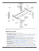
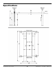
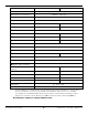
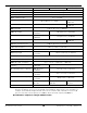
Table Of Contents
- HD-9 Manual
- Table of Contents
- Introduction
- Shipping Information
- Safety Considerations
- Components
- Specifications
- Frequently Asked Questions
- Installation Checklist
- Installation
- Being Safe
- Using Tools
- Planning for Electrical Work
- Selecting a Location
- Checking Clearances
- Deciding the Lift Orientation
- Creating Chalk Line Guides
- Unloading and Unpacking
- Moving the Posts into Position
- Installing the Crosstubes
- About Safety Locks
- Installing the Ladders and Top Cap
- Raising the Crosstubes
- Securing the Ladders
- Removing the Sheaves
- Installing the Runways
- Installing the First End of the Flex Tube
- Routing the Lifting Cables
- Working with Compression Fittings and Tubing
- Installing the Air Lines
- Installing the Return Line
- Hydraulic Fluid Contamination
- About Thread Sealants
- Installing the Hydraulic Hose
- Installing the Power Unit
- Filling the Hydraulic Fluid Reservoir
- Installing the Second End of the Flex Tube
- Installing the Pushbutton Air Valve
- Connecting the Return Line
- Connecting the Hydraulic Hose
- Contacting the Electrician
- Connecting the Power Source
- Installing a Power Disconnect Switch
- Installing a Thermal Disconnect Switch
- About Effective Embedment
- Anchoring the Posts
- Final Leveling
- Installing Accessories
- Lubricating the Lift
- Bleeding the Hydraulic Cylinder
- Test the Lift
- Final Checklist
- Outdoor usage
- Operation
- Maintenance
- Troubleshooting
- Wiring Diagrams
- Labels
- Parts Drawings
- Automotive Lift Institute (ALI) Store

HD-9 Series Four-Post Lifts 6 P/N 5900123 — Rev. M1 — March 2020
Components
The main components of your Lift include:
• Power Post. The Post that holds the Power Unit.
The Power Post can be in either of two
locations
. You can tell the Power Post from the other Posts because it has two Mounting
Brackets on it. Mount the Power Unit on one of the two Mounting Brackets.
• The other three Posts. These Posts are interchangeable.
• Power Unit. An electric/hydraulic unit that connects to an electric power source and then
provides Hydraulic Fluid to the Hydraulic Cylinder that raises and lowers the Runways.
• Powerside Runway. On the same side as the Power Post. The Powerside Runway has the
Hydraulic Cylinder and the Lifting Cables under them. The Powerside Runway
must
go next to the
Power Post.
• Offside Runway. The other Runway. It does not have a Hydraulic Cylinder or Lifting Cables
under.
• Flex Tube. Not shown. A flexible, black tube that attaches to an opening on the Powerside
Runway on one end and to the bottom of the Flex Tube Bracket Plate (near the Power Unit) on the
other end. Used for routing the Air Line, Return Line, and Hydraulic Hose to the Power Unit.
• Utility Rails. Hold the optional Rolling Jacks. Utility Rails
must
go on the inside of the Lift.
• Crosstubes. Go at each end of the Lift. The Crosstubes are hollow; the Lifting Cables that raise
and lower the Runways are routed through the Crosstubes. The Crosstubes are not
interchangeable: Each Crosstube has an opening (called a ‘Window’) that faces the inside of the
Lift.
Make sure to install the Lift so that the
Windows open to the inside of the Lift
only
.
• Drive-up Ramps. One for each Runway. Use them to drive onto and off of the Runways.
• Tire Stops. Located at the Front of the Lift, Tire Stops prevent the Vehicle’s Front Tires from
going any further forward. Additionally, we strongly recommend chocking the Vehicle’s Rear Tires.
• Safety Locks. Once engaged, they hold the Runways in position, even if the power goes out or
there is a leak in the Hydraulic Hoses. Your Lift has a column of Safety Locks in each post, spaced
every four inches. This lets you lock the Runways at just the right height for what you want to do.
This Lift also has a backup Slack Safety system; refer to About Safety Locks for more
information.
Only leave the Runways on the ground or engaged on a Safety Lock.
• Pushbutton Air Valve. Includes a Pushbutton that moves the Safety Locks away from the
Ladder so that they do not engage as you lower the Runways. Used only to lower the Runways.
Usually located next to the Power Post.
• Ladders. Pieces of steel that gets installed at the back of each Post; these are part of the Safety
Lock system.