
Use and Care Manual
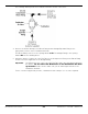


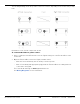

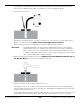
Table Of Contents
- HD-9 Manual
- Table of Contents
- Introduction
- Shipping Information
- Safety Considerations
- Components
- Specifications
- Frequently Asked Questions
- Installation Checklist
- Installation
- Being Safe
- Using Tools
- Planning for Electrical Work
- Selecting a Location
- Checking Clearances
- Deciding the Lift Orientation
- Creating Chalk Line Guides
- Unloading and Unpacking
- Moving the Posts into Position
- Installing the Crosstubes
- About Safety Locks
- Installing the Ladders and Top Cap
- Raising the Crosstubes
- Securing the Ladders
- Removing the Sheaves
- Installing the Runways
- Installing the First End of the Flex Tube
- Routing the Lifting Cables
- Working with Compression Fittings and Tubing
- Installing the Air Lines
- Installing the Return Line
- Hydraulic Fluid Contamination
- About Thread Sealants
- Installing the Hydraulic Hose
- Installing the Power Unit
- Filling the Hydraulic Fluid Reservoir
- Installing the Second End of the Flex Tube
- Installing the Pushbutton Air Valve
- Connecting the Return Line
- Connecting the Hydraulic Hose
- Contacting the Electrician
- Connecting the Power Source
- Installing a Power Disconnect Switch
- Installing a Thermal Disconnect Switch
- About Effective Embedment
- Anchoring the Posts
- Final Leveling
- Installing Accessories
- Lubricating the Lift
- Bleeding the Hydraulic Cylinder
- Test the Lift
- Final Checklist
- Outdoor usage
- Operation
- Maintenance
- Troubleshooting
- Wiring Diagrams
- Labels
- Parts Drawings
- Automotive Lift Institute (ALI) Store

HD-9 Series Four-Post Lifts 54 P/N 5900123 — Rev. M1 — March 2020
Connecting the Power Source
The standard Power Unit for your Lift is 220 VAC, 60 Hz, single phase. The Power Unit must be
connected to an appropriate power source.
Refer to Wiring Diagrams for wiring information.
⚠ DANGER All wiring
must
be performed by a licensed, certified Electrician. Do not perform
any maintenance or installation on the Lift without first making sure that main
electrical power has been disconnected from the Lift and
cannot
be re-energized
until all procedures are complete. If your organization has Lockout/Tagout policies,
make sure to implement them after connecting to a power source.
Important electrical information:
• Improper electrical installation can damage the motor; this is not covered under warranty.
• Use a separate circuit breaker for each Power Unit.
• Protect each circuit with a time-delay fuse or circuit breaker. For a 220 VAC, single phase circuit,
use a 25 amp or greater fuse.
The Hydraulic Power Ports are usually labeled P1/P2 on the Power Unit; the Hydraulic Return Ports
are commonly labeled T1/T2 or CV1/CV2.
The following drawing shows the standard configuration for the Power Unit.
Not drawn to scale. Not all components shown.