
Use and Care Manual
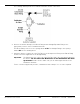


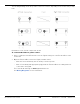

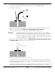
Table Of Contents
- HD-9 Manual
- Table of Contents
- Introduction
- Shipping Information
- Safety Considerations
- Components
- Specifications
- Frequently Asked Questions
- Installation Checklist
- Installation
- Being Safe
- Using Tools
- Planning for Electrical Work
- Selecting a Location
- Checking Clearances
- Deciding the Lift Orientation
- Creating Chalk Line Guides
- Unloading and Unpacking
- Moving the Posts into Position
- Installing the Crosstubes
- About Safety Locks
- Installing the Ladders and Top Cap
- Raising the Crosstubes
- Securing the Ladders
- Removing the Sheaves
- Installing the Runways
- Installing the First End of the Flex Tube
- Routing the Lifting Cables
- Working with Compression Fittings and Tubing
- Installing the Air Lines
- Installing the Return Line
- Hydraulic Fluid Contamination
- About Thread Sealants
- Installing the Hydraulic Hose
- Installing the Power Unit
- Filling the Hydraulic Fluid Reservoir
- Installing the Second End of the Flex Tube
- Installing the Pushbutton Air Valve
- Connecting the Return Line
- Connecting the Hydraulic Hose
- Contacting the Electrician
- Connecting the Power Source
- Installing a Power Disconnect Switch
- Installing a Thermal Disconnect Switch
- About Effective Embedment
- Anchoring the Posts
- Final Leveling
- Installing Accessories
- Lubricating the Lift
- Bleeding the Hydraulic Cylinder
- Test the Lift
- Final Checklist
- Outdoor usage
- Operation
- Maintenance
- Troubleshooting
- Wiring Diagrams
- Labels
- Parts Drawings
- Automotive Lift Institute (ALI) Store

HD-9 Series Four-Post Lifts 51 P/N 5900123 — Rev. M1 — March 2020
The following drawing shows the Pushbutton Air Valve and its connections.
4. Connect the Air Line Compression Elbow Fitting and the Straight Expander Fitting to the
appropriate locations on the Pushbutton Air Valve.
The Elbow Fitting connects to the opening labelled CYL. The Straight Fitting to the opening
labelled IN. See the drawing above.
5. Attach the Air Line (coming out of the Flex Tube) to the Compression Fitting on the Elbow Fitting
and the customer-supplied air to the Straight Fitting.
Important: The Return Line also comes out of the Flex Tube and is the same kind of tubing as
the Air Line.
Do not attach the Return Line to the Pushbutton Air Valve
by mistake
. Double check to make sure you are attaching the Air Line to the
Pushbutton Air Valve.
For the customer-supplied air pressure, a minimum of 50 to 150 psi / 3 to 25 cfm is required.