
Use and Care Manual
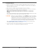
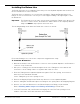
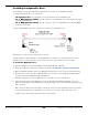
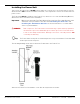
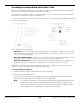


Table Of Contents
- HD-9 Manual
- Table of Contents
- Introduction
- Shipping Information
- Safety Considerations
- Components
- Specifications
- Frequently Asked Questions
- Installation Checklist
- Installation
- Being Safe
- Using Tools
- Planning for Electrical Work
- Selecting a Location
- Checking Clearances
- Deciding the Lift Orientation
- Creating Chalk Line Guides
- Unloading and Unpacking
- Moving the Posts into Position
- Installing the Crosstubes
- About Safety Locks
- Installing the Ladders and Top Cap
- Raising the Crosstubes
- Securing the Ladders
- Removing the Sheaves
- Installing the Runways
- Installing the First End of the Flex Tube
- Routing the Lifting Cables
- Working with Compression Fittings and Tubing
- Installing the Air Lines
- Installing the Return Line
- Hydraulic Fluid Contamination
- About Thread Sealants
- Installing the Hydraulic Hose
- Installing the Power Unit
- Filling the Hydraulic Fluid Reservoir
- Installing the Second End of the Flex Tube
- Installing the Pushbutton Air Valve
- Connecting the Return Line
- Connecting the Hydraulic Hose
- Contacting the Electrician
- Connecting the Power Source
- Installing a Power Disconnect Switch
- Installing a Thermal Disconnect Switch
- About Effective Embedment
- Anchoring the Posts
- Final Leveling
- Installing Accessories
- Lubricating the Lift
- Bleeding the Hydraulic Cylinder
- Test the Lift
- Final Checklist
- Outdoor usage
- Operation
- Maintenance
- Troubleshooting
- Wiring Diagrams
- Labels
- Parts Drawings
- Automotive Lift Institute (ALI) Store

HD-9 Series Four-Post Lifts 45 P/N 5900123 — Rev. M1 — March 2020
Installing the Hydraulic Hose
The Hydraulic Hose moves Hydraulic Fluid from the Power Unit to the Hydraulic Cylinder.
To install the Hydraulic Hose, you will need:
• The Hydraulic Hose. The Hydraulic Hose has a Curved end and Straight end.
• JIC to NPT Hydraulic Fitting. The JIC end goes to the Hydraulic Hose and the NPT end goes
to the Hydraulic Cylinder.
• JIC to ORB Hydraulic Fitting. The JIC connector goes to the Hydraulic Hose and the ORB
end to the Power Unit.
The following drawing shows the connections to make to the Hydraulic Hose.
Drawing not to scale. Not all components are shown.
The following procedure is based on the drawing above, but it does not matter which end of the
Hydraulic Hose is connected to the Power Unit; choose the option that best fits your setup.
To install the Hydraulic Hose:
1. Find the Hydraulic Hose and a Hydraulic Elbow Fitting (04 JIC – 06 NPT).
2. Clean the Hydraulic components using the information in Hydraulic Fluid Contamination.
3. On the Hydraulic Cylinder, remove the Shipping Plug from the connector at the Piston Rod end.
4. Attach the NPT end of the JIC-to-NPT Fitting to the connector on the Hydraulic Cylinder (where
you just removed the Shipping Plug) and tighten it.
5. Attach the Straight end of the Hydraulic Hose to the JIC connector and tighten it.
6. Take the Curved end of the Hydraulic Hose and, starting at the Hydraulic Cylinder, route the
Curved end through the Retaining Rings (along inside edge of the Powerside Runway) and the Flex
Tube opening.
Once done, the Curved end should be coming out of the Flex Tube opening near the Power Unit.
7. Leave the Curved end of the Hydraulic Hose coming out of the Flex Tube opening for now.
It will be connected to the Power Unit later in the installation.