
Use and Care Manual
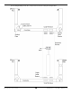
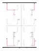
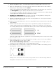
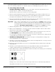
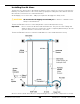
Table Of Contents
- HD-9 Manual
- Table of Contents
- Introduction
- Shipping Information
- Safety Considerations
- Components
- Specifications
- Frequently Asked Questions
- Installation Checklist
- Installation
- Being Safe
- Using Tools
- Planning for Electrical Work
- Selecting a Location
- Checking Clearances
- Deciding the Lift Orientation
- Creating Chalk Line Guides
- Unloading and Unpacking
- Moving the Posts into Position
- Installing the Crosstubes
- About Safety Locks
- Installing the Ladders and Top Cap
- Raising the Crosstubes
- Securing the Ladders
- Removing the Sheaves
- Installing the Runways
- Installing the First End of the Flex Tube
- Routing the Lifting Cables
- Working with Compression Fittings and Tubing
- Installing the Air Lines
- Installing the Return Line
- Hydraulic Fluid Contamination
- About Thread Sealants
- Installing the Hydraulic Hose
- Installing the Power Unit
- Filling the Hydraulic Fluid Reservoir
- Installing the Second End of the Flex Tube
- Installing the Pushbutton Air Valve
- Connecting the Return Line
- Connecting the Hydraulic Hose
- Contacting the Electrician
- Connecting the Power Source
- Installing a Power Disconnect Switch
- Installing a Thermal Disconnect Switch
- About Effective Embedment
- Anchoring the Posts
- Final Leveling
- Installing Accessories
- Lubricating the Lift
- Bleeding the Hydraulic Cylinder
- Test the Lift
- Final Checklist
- Outdoor usage
- Operation
- Maintenance
- Troubleshooting
- Wiring Diagrams
- Labels
- Parts Drawings
- Automotive Lift Institute (ALI) Store

HD-9 Series Four-Post Lifts 36 P/N 5900123 — Rev. M1 — March 2020
Before routing the Cables, extend the Piston on the Hydraulic Cylinder.
To extend the Piston:
1. Remove the Shipping Plug from the Return Line Connector.
The Return Line Connector is on the Cylinder end closest to where the Power Unit will be.
2. Attach an air pressure source to the Return Line Connector.
3. Use the air pressure to extend the Hydraulic Cylinder’s Piston and Retaining Plate.
Do not exceed 50 psi
.
If the Cylinder does not move, stop using air pressure; instead, use a pulling device (such as a
Come Along Tool) to extend the Piston and Retaining Plate; be care not to damage the Piston.
4. Reinstall the Shipping Plug to the Return Line Connector.
The following procedure assumes you have nearby the four Lifting Cables and Sheaves you removed
prior to installing the Runways.
To route Lifting Cables A and C:
1.
Starting with Lifting Cable A
, move the entire thing to just under the Large Window it goes
through, near the bottom of Post A.
Check the label to make sure you have the correct Lifting Cable.
2. Remove the Nut and Washer from the Threaded End (but keep it nearby, you will need it soon).
3. Route the Threaded End of Lifting Cable A into its Large Window on the Crosstube, push it
towards Post A, and then pull the Threaded End out of the Crosstube at the bottom of the Gusset.
4. Route the Threaded End of Lifting Cable A under where the Gusset Sheave will go when it is
reinstalled, then route it up past the top of the Crosstube Gusset.
The following drawing shows how to route the Lifting Cable through the Gusset.
Important: When routing a Lifting Cable in its Post, the Cable must go
under
the Gusset
Sheave and be on the side of the Slack Safety Sheave. When the Cables are pulled
tight, the Cable prevents the Slack Safety from engaging, which is what you want. If
the Cable is
not in this exact location
, the Slack Safeties will
not
work
correctly.