
Use and Care Manual
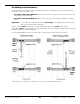
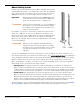
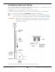

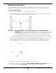
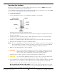
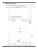
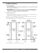
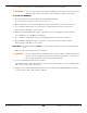
Table Of Contents
- HD-9 Manual
- Table of Contents
- Introduction
- Shipping Information
- Safety Considerations
- Components
- Specifications
- Frequently Asked Questions
- Installation Checklist
- Installation
- Being Safe
- Using Tools
- Planning for Electrical Work
- Selecting a Location
- Checking Clearances
- Deciding the Lift Orientation
- Creating Chalk Line Guides
- Unloading and Unpacking
- Moving the Posts into Position
- Installing the Crosstubes
- About Safety Locks
- Installing the Ladders and Top Cap
- Raising the Crosstubes
- Securing the Ladders
- Removing the Sheaves
- Installing the Runways
- Installing the First End of the Flex Tube
- Routing the Lifting Cables
- Working with Compression Fittings and Tubing
- Installing the Air Lines
- Installing the Return Line
- Hydraulic Fluid Contamination
- About Thread Sealants
- Installing the Hydraulic Hose
- Installing the Power Unit
- Filling the Hydraulic Fluid Reservoir
- Installing the Second End of the Flex Tube
- Installing the Pushbutton Air Valve
- Connecting the Return Line
- Connecting the Hydraulic Hose
- Contacting the Electrician
- Connecting the Power Source
- Installing a Power Disconnect Switch
- Installing a Thermal Disconnect Switch
- About Effective Embedment
- Anchoring the Posts
- Final Leveling
- Installing Accessories
- Lubricating the Lift
- Bleeding the Hydraulic Cylinder
- Test the Lift
- Final Checklist
- Outdoor usage
- Operation
- Maintenance
- Troubleshooting
- Wiring Diagrams
- Labels
- Parts Drawings
- Automotive Lift Institute (ALI) Store

HD-9 Series Four-Post Lifts 21 P/N 5900123 — Rev. M1 — March 2020
Installing the Crosstubes
Your Lift has two Crosstubes, both hollow, which allows the Lifting Cables to be run through them to
the Posts. The two Crosstubes are:
• Crosstube with Large Windows: Goes on the end of the Lift opposite of the Power Post, with
the Windows facing the inside.
• Crosstube with Small Windows: Goes next to the Power Post, with the Windows facing the
inside.
Important: It is possible to install the Crosstubes
incorrectly
in several different ways. Take your
time now and get it right the first time.
The Crosstubes
must
be installed so that their Windows open to the
inside
of the Lift; the
Crosstubes
must
also be installed so that their Windows are on the Powerside Runway side of the Lift
(the Runway with the Hydraulic Cylinder).
The following drawing shows the two Crosstube setups based on the Power Post location.
Top View. Not to scale. Some components not shown or exaggerated for clarity.