645 Lemonwood Dr. Santa Paula, CA 93060 USA Toll Free: (800) 253-2363 Tel: (805) 933-9970 bendpak.com HD-9 Four-Post Lift Installation and Operation Manual Manual P/N 5900123 — Manual Revision M1 — March 2020 Models: • HD-9ST • HD-9STX • HD-9 • HD-9XL • HD-9XW HD-9ST shown. Designed and engineered by BendPak Inc. in Southern California, USA. Made in China. ⚠ DANGER Read the entire contents of this manual before using this product.
Manual. HD-9 Four-Post Lifts, Installation and Operation Manual, Manual P/N 5900123, Manual Revision M1, Released March 2020. Copyright. Copyright © 2020 by BendPak Inc. All rights reserved. You may make copies of this document if you agree that: you will give full attribution to BendPak Inc., you will not make changes to the content, you do not gain any rights to this content, and you will not use the copies for commercial purposes. Trademarks.
Table of Contents Introduction 3 Operation 68 Shipping Information 4 Maintenance 71 Safety Considerations 4 Troubleshooting 73 Components 6 Wiring Diagrams 74 Specifications 8 Labels 76 FAQs 11 Parts Drawings 79 Installation Checklist 12 ALI Store 91 Installation 13 Introduction This manual describes the following ALI- and CE-certified Four-Post Lifts: • • • • • HD-9ST. Four-Post Lift with an overall width of 100.25" (8.4 feet), raising Vehicles up to 9,000 lbs (4,082 kg).
Shipping Information Your equipment was carefully checked before shipping. Nevertheless, you should thoroughly inspect the shipment before you sign to acknowledge that you received it. When you sign a bill of lading, it tells the carrier that the items on the invoice were received in good condition. To protect yourself, do not sign until after you have inspected the shipment.
• BendPak recommends making a thorough inspection of the product at least once a year. Replace any damaged or severely worn parts, decals, or warning labels. Symbols Following are the symbols used in this manual: ⚠ DANGER ⚠ WARNING ⚠ CAUTION NOTICE Tip Calls attention to an immediate hazard that will result in death or severe injury. Calls attention to a hazard or unsafe practice that could result in death or severe personal injury.
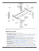
Components The main components of your Lift include: • • • • • • • • • • • • • Power Post. The Post that holds the Power Unit. The Power Post can be in either of two locations. You can tell the Power Post from the other Posts because it has two Mounting Brackets on it. Mount the Power Unit on one of the two Mounting Brackets. The other three Posts. These Posts are interchangeable. Power Unit.
Drawing shows the two possible Power Post locations; only one Post has the Brackets for mounting the Power Unit. Not all components are shown. Optional Accessories There are additional products you can use with your Lift: • • • • • Aluminum Drive-up Ramps. The Aluminum Drive-up Ramps are a low-profile alternative to the standard Drive-up Ramps that come with your Lift. See the Aluminum Approach Ramps page on the BendPak website for more information. Aluminum Platforms.
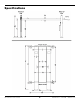
Specifications HD-9 Series Four-Post Lifts 8 P/N 5900123 — Rev.
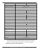
Model HD-9ST HD-9STX Lifting Capacity 9,000 lbs / 4,082 kg Max capacity at Front Axle 4,500 lbs / 2,041 kg Max capacity at Rear Axle 4,500 lbs / 2,041 kg 5" / 125 mm a Min. runway height b Maximum rise 70" (5.10 feet) / 1,778 mm 82" (6.10 feet) / 2,083 mm c Maximum lifting height 75" (6.3 feet) / 1,903 mm 87" (7.3 feet) / 2,208 mm 100.25" (8.4 feet) / 2,546 mm d Overall width e Outside length 174" (14.6 feet) / 4,420 mm 198" (16.6 feet) / 5,029 mm f Overall length 200.5" (16.
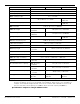
Model HD-9 HD-9XL Lifting capacity Max capacity at Front Axle Max capacity at Rear Axle 9,000 lbs / 4,082 kg 4,500 lbs / 2,041 kg 4,500 lbs / 2,041 kg a Min. runway height b Maximum rise 70" (5.10 feet) / 1,778 mm c Maximum lifting height 75" (6.3 feet) / 1,903 mm 4.5" / 114 mm d Overall width e Outside length f Overall length g Height of post h Distance between posts i Drive-thru clearance j Runway width k Runway length l Width between runways m Runway centerline n Outside edge of runways Min.
Frequently Asked Questions Question: Answer: What kinds of Vehicles can I put on my Lift? Cars, trucks, SUVs; anything that fits on the Runways, up to 9,000 lbs (4,082 kg). Q: Can any of the four Posts be the ‘Power Post’? A: No; the only two possible locations for the Power Post are either the Front Driver-Side or the Rear Passenger-Side. This will be explained later.
Installation Checklist Following are the steps needed to install your Lift. Perform them in the order shown. ☐ 1. Review the safety rules. ☐ 2. Make sure you have the necessary tools. ☐ 3. Plan for Electrical work. ☐ 4. Select the installation location. ☐ 5. Check the Clearances. ☐ 6. Decide the Lift Orientation. ☐ 7. Unload and unpack the Lift components. ☐ 8. Create Chalk Line Guides. ☐ 9. Move the Posts into position. ☐ 10. Install the Crosstubes. ☐ 11. About Safety Locks. ☐ 12.
Installation The installation process takes multiple steps. Perform them in the order listed. Read the entire Installation section before beginning the install; this gives you a better understanding of the process as a whole. ⚠ WARNING Only use the factory-supplied parts that came with your Lift. If you use parts from a different source, you void your warranty and compromise the safety of everyone who installs or uses the Lift. If you are missing parts, visit bendpak.
Planning for Electrical Work You will need to have a licensed, certified Electrician available at some point in the installation. ⚠ DANGER All wiring must be performed by a licensed, certified Electrician. Notify your Electrician in advance so that they come prepared with an appropriate Power Cord with a Plug for connecting to the power source, a Power Disconnect Switch, and a Thermal Disconnect Switch. Refer to Contacting the Electrician for more information.
Selecting a Location When selecting the location for your Lift, consider: • • • • • • Architectural plans. Consult the architectural plans for your desired installation location. Make sure there are no issues between what you want to do and what the plans show. Available space. Make sure there is enough space for the Lift: front, back, sides, and above. Refer to Specifications for measurements. Overhead Clearance.
• Non-Slip Rubber Pads. If you do not plan to anchor the Lift (and want to use the optional Caster Kit), you could go to your local hardware store and get non-slip Rubber Pads and size them to fit the bottom of the Base Plates; the Pads will protect against scratches on special flooring if the Lift accidentally shifts as a result of not anchoring the Lift. Use the Caster Kit to raise the Lift and then put the Pads into place.
Deciding the Lift Orientation Before going any further, decide how you want to orient your Lift. This decision affects where you will place your Power Post and also the positioning of the Runways, which are not interchangeable. One Runway has the Hydraulic Cylinder underneath it and is the starting point for the Lifting Cables. The other Runway, called the Offside Runway, does not have anything underneath it.
Creating Chalk Line Guides Create the Chalk Line Guides so that the outside edges of all four Posts fit into the four corners created by the Chalk Line Guides. See Specifications to determine the Overall Width and Outside Length values for your Lift. Note: Do not use the Overall Length value; this includes the Ramps, which are not taken into consideration for creating Chalk Line Guides. Top View. Not drawn to scale. Not all components shown. HD-9 Series Four-Post Lifts 18 P/N 5900123 — Rev.
To create Chalk Line Guides: 1. Create the Front Chalk Line where you want the Front of the Lift. The Front of the Lift is the end opposite the Drive-up Ramps. Make the Front Chalk Line longer (about 12 inches) than the Overall Width setting. 2. Create the two Side Chalk Lines at 90° angles to the Front Chalk Line and parallel to each other. Make the Side Chalk Lines longer (about 12 inches on each end) than the Outside Length setting. The Side Chalk Lines must be parallel to each other.
Unloading and Unpacking Once the components are unloaded, they are your responsibility to move around. As the Lift includes a number of heavy pieces, the closer you unload them to the installation location, the better off you are. ⚠ CAUTION ⚠ WARNING Some Lift components are very heavy; if handled incorrectly, they can damage materials like tile, sandstone, and brick. Try to handle the Lift components twice: once when delivered and once when moved into position.
Installing the Crosstubes Your Lift has two Crosstubes, both hollow, which allows the Lifting Cables to be run through them to the Posts. The two Crosstubes are: • • Crosstube with Large Windows: Goes on the end of the Lift opposite of the Power Post, with the Windows facing the inside. Crosstube with Small Windows: Goes next to the Power Post, with the Windows facing the inside. Important: It is possible to install the Crosstubes incorrectly in several different ways.
To install the Crosstubes: 1. Orient the Crosstubes in their required locations. Both Windows must be on the ends of the Powerside Runway and facing the inside of the Lift. 2. Put black Slide Blocks into place on the outside ends of each Gusset (4 Slide Blocks per Gusset, 8 per Crosstube, 16 total for the Lift). Align the holes in the Slide Blocks with the rods on the side of the Gusset, then press the Slide Blocks in. Make sure the Slide Blocks are oriented so that they create a Slot when pushed in.
About Safety Locks Safety Locks hold the Runways in place. Once engaged, Safety Locks hold the Runways in place, even if the power goes out or the Hydraulic Hoses break or leak. The Safety Locks are spaced every four inches / 100 mm. Each Post has its own Ladder and set of Safety Locks. Important: ⚠ WARNING Simply raising the Runways does not engage them on the Safety Locks. You must back the Runways down onto the Safety Locks to engage them.
Installing the Ladders and Top Cap Each Post has a Ladder; each Ladder gets installed on the inside back of a Post. Ladders are secured at the top and the bottom. All four Ladders are identical. It is not necessary to slide the Ladders in from the very top of the Post. The Top Caps secure the Ladder at the top of each Post and hold the ends of the Lifting Cables. Make sure to install each Ladder through both slots on each Crosstube Gusset.
To install the Ladders and the Top Caps: 1. Take a Ladder and slide it down the back of the Post, with the Bolt Hole end at the bottom. Make sure the Ladder goes through both Slots on each Gusset. There is a Slot at the top of the Gusset and another Slot at the bottom of the Gusset, both formed by the Slide Blocks. ⚠ WARNING It is easy to see the top Slot created by the Slide Blocks. It is difficult to see the bottom Slot, but it is required that the Ladder goes through both Slots.
Raising the Crosstubes You need to manually raise the Crosstubes, which makes it easier to complete the rest of the installation tasks. The Crosstubes need to be raised the same height, to the same Safety Lock. To raise the Crosstubes: 1. Use a Forklift or Shop Crane to carefully raise each Crosstube. You want to raise the Crosstubes at least two feet off the ground, to have enough room to work under it, making it easier to route the Lifting Cables and Lines.
Securing the Ladders Because it is much easier to secure the Ladders at the bottom of each Post after the Crosstubes have been raised, that procedure is described here. The following procedure assumes that the Ladders are in place and secured at the top. If this is not the case, return to Installing the Ladders and Top Cap. To secure the Ladders: 1. Locate a Bolt, Washer, Spacer, second Washer, and Nut for each Ladder. Side view of the Post. Not all components shown. 2.
Removing the Sheaves In order to route the Lifting Cables, you need to remove the Cable Sheaves on the underside of the Powerside Runway and the four Gusset Sheaves and their Lock Pins. When you remove the Sheaves, keep the components together. You will be reinstalling them at the same location, using the same components. Drawing combines Top and Side views. Not necessarily to scale. Not all components shown. HD-9 Series Four-Post Lifts 28 P/N 5900123 — Rev.
Installing the Runways Your Lift has two Runways: • • Powerside Runway: Holds the Hydraulic Cylinder underneath it. Has a hole on the outside Rear that lets you route the Hydraulic Hose, Air Lines, and Return Line to the Power Unit. Cable routing starts under the Powerside Runway. Offside Runway: The Offside Runway does not have a Hydraulic Cylinder under it, nor are there any Lifting Cables under it.
Use a Forklift or Shop Crane to raise the Runways and move them into position. ⚠ WARNING Pay close attention when moving the Runways into position; they are very heavy and long, and could shift position or fall, potentially causing serious injury. To install the Runways: 1. Correctly orient the Powerside Runway and the Offside Runway. The Powerside Post must go next to the Power Post. 2. On the underside of the Powerside Runway, make sure the Sheaves have been removed. 3.
Installing the First End of the Flex Tube The Flex Tube is a flexible, black tube that attaches to an opening on the Powerside Runway on one end and to the bottom of the Flex Tube Bracket Plate (near the Power Unit) on the other end. The Flex Tube consolidates and protects three different Cables that come out from under the Powerside Runway on their way to the Power Unit: The Return Line, the Air Line, and Hydraulic Hose. The Flex Tube is about 52 in / 1,320 mm long and about 1.5 in / 38 mm wide.
Routing the Lifting Cables Before routing the Lifting Cables on your Lift, you need to know the following: • • • BendPak strongly recommends using protective gloves when working with the Lifting Cables. Each Lift has four Lifting Cables of varying lengths and can only make one connection. All Lifting Cables have a Button End and a Threaded End.
• • • • • • In the following drawings, the Cables and Cable Sheaves are labeled A, B, C, and D. These letters are not on the label on the Threaded end. You have to match the Cable letter with the length. The four Lifting Cables for the HD-9ST are: o A: 2,926 mm / 9.7 feet / 115.25 inches o B: 4,356 mm / 14.4 feet / 171.5 inches o C: 7,048 mm / 23.2 feet / 277.5 inches o D: 8,476 mm / 27.10 feet / 333.75 inches The four Lifting Cables for the HD-9STX are: o A: 3,240 mm / 11 feet / 127.
The following drawing shows the components involved in routing the Lifting Cables. HD-9 Series Four-Post Lifts 34 P/N 5900123 — Rev.
HD-9 Series Four-Post Lifts 35 P/N 5900123 — Rev.
Before routing the Cables, extend the Piston on the Hydraulic Cylinder. To extend the Piston: 1. Remove the Shipping Plug from the Return Line Connector. The Return Line Connector is on the Cylinder end closest to where the Power Unit will be. 2. Attach an air pressure source to the Return Line Connector. 3. Use the air pressure to extend the Hydraulic Cylinder’s Piston and Retaining Plate. Do not exceed 50 psi.
5. With the Lifting Cable in place, reinstall the Gusset Sheave and the Cable Lock Pin in Post A. 6. Make sure Lifting Cable A is correctly positioned: in between the Gusset Sheave and the Slack Safety Sheave, with the Cable Lock Pin under it. 7. Push the Threaded End of Lifting Cable A up to and through the Top Cap (at the top of the Post) and hand tighten it in place with the Nut and Washer you removed earlier.
Routing Lifting Cables B and D is the same process as routing Lifting Cables A and C, just to the other two Posts and using a different set of Sheaves. Refer to the drawings in the previous section. To route Lifting Cables B and D: 1. Starting with Lifting Cable B, move the entire thing to under the Large Window it goes through, opposite of Cables A and C (already in place). Check the label to make sure you have the correct Lifting Cable. 2.
Working with Compression Fittings and Tubing Your Lift comes with a roll of ¼ inch, black, polyethylene Tubing (also called Poly-Flo® Tubing) that is used with Compression Fittings in two ways: for the Return Line and for the Air Lines. Important: Note: While both lines use Tubing and Compression Fittings, the Return Line and Air Lines are used for completely separate purposes; do not connect the two together. Compression Fittings are different from Hydraulic Fittings.
Installing the Air Lines The Air Lines use air pressure to disengage the Safety Locks in each Post so that you can lower the Runways. You will need more of the ¼ inch, black, polyethylene Tubing that came with the Lift and three Air Line Tee Connectors to install the Air Lines. An Air Supply (3 to 25 cfm at 50 — 150 psi) is required to disengage the Safety Locks. ⚠ CAUTION Do not let the Air Supply exceed 150 psi; the Air Lines could burst or the Safety Locks malfunction.
To install the Air Lines: 1. Find the roll of supplied ¼ inch, black, polyethylene Tubing and three Air Line Tee Connectors. 2. Measure the distances for each of the seven (7) Tubing pieces you will need (see the drawing on the previous page) for the Air Lines. 3. Cut seven pieces of Tubing to the measured lengths from the roll of Tubing. 4. Connect the various pieces of Tubing to the Air Line Tee Connectors on the Lift, as shown in the drawing on the previous page for the locations of the Tubing pieces.
Installing the Return Line The Return Line takes excess Hydraulic Fluid coming out of the Hydraulic Cylinder and sends it back into the Fluid Reservoir on the Power Unit. The Return Line is a single piece of ¼ inch, black, polyethylene Tubing with Elbow Compression Fittings on each end. You need to cut off a piece of the supplied Tubing of the right length to create the Return Line. Important: The Return Line uses the same ¼ inch, black, polyethylene Tubing as the Air Lines.
IMPORTANT! PLEASE READ NOW Hydraulic Fluid Contamination Hydraulic Fluid Contamination poses a serious issue for your Lift; contaminants such as water, dirt, or other debris can get into the Hydraulic Hoses and Fittings on your Lift, making your new Lift inoperable. Your Lift is shipped with clean components; however, BendPak strongly recommends that you take secondary precaution and clean all Hydraulic Hoses and Fittings prior to making connections.
About Thread Sealants We recommend using a Liquid Thread Sealant (like Loctite™ 5452 or similar PTFE Thread Sealant) to seal the Hydraulic components on your Lift. Liquid Thread Sealant lubricates and fills the gaps between the Fitting threads, and leaves no residue that could contaminate the Hydraulic Fluid. Other types of Thread Sealants (like Teflon Tape) can shred during installation or removal and eventually enter the Hydraulic System.
Installing the Hydraulic Hose The Hydraulic Hose moves Hydraulic Fluid from the Power Unit to the Hydraulic Cylinder. To install the Hydraulic Hose, you will need: • • • The Hydraulic Hose. The Hydraulic Hose has a Curved end and Straight end. JIC to NPT Hydraulic Fitting. The JIC end goes to the Hydraulic Hose and the NPT end goes to the Hydraulic Cylinder. JIC to ORB Hydraulic Fitting. The JIC connector goes to the Hydraulic Hose and the ORB end to the Power Unit.
Installing the Power Unit This section describes how to install, but not make the connections to, the Power Unit for your Lift. An Electrician is not needed to install the Power Unit; one is required to connect the Power Unit to its power source. The Power Unit must be installed on the Power Post; attach it to one of the two Mounting Brackets, whichever is more convenient for the installation.
To install the Power Unit: 1. Find the four supplied Hex Head Bolts, Flat Washers, Nyloc Nuts, and Vibration Plate. 2. Line up the holes on the Power Unit Back Plate with the four holes in the Mounting Bracket you want to use. If you are going to install the Flex Tube Bracket Plate and/or the Zero Angle Bracket at the same time as the Power Unit, now is the time to put those into place. 3.
Installing the Second End of the Flex Tube Once the Power Unit is installed, you can install the second end of the Flex Tube (the other end was connected to the Powerside Runway earlier in the installation). The Flex Tube consolidates and protects the lines that come out from under the Powerside Runway: the Air Line, the Return Line, and the Hydraulic Hose. To connect the Flex Tube to the Power Unit, you first need to connect the Flex Tube Bracket Plate and the Flex Tube Angle Plate.
The following drawing describes how to position the Flex Tube Bracket Plate between the Mounting Bracket and Back Plate. Side view of where the Power Unit attaches to the Power Post. Not necessarily to scale. 3. Connect the Flex Tube Angle Plate to the Flex Tube Bracket Plate so that the holes for the Flex Tubes are best positioned for connecting the Return Line, the Air Line, and the Hydraulic Hose. The Flex Tube Angle Plate can be connected on either side of the Flex Tube Bracket Plate. 4.
Installing the Pushbutton Air Valve Once the Power Unit and the Flex Tube are installed, you can install the Pushbutton Air Valve, which requires the Zero Angle Bracket (which may already have been installed). The Pushbutton Air Valve is used to lower the Runways. It can go on either side of the Power Unit, but we recommend placing it on the side facing away from the Lift to be out of the way.
The following drawing shows the Pushbutton Air Valve and its connections. 4. Connect the Air Line Compression Elbow Fitting and the Straight Expander Fitting to the appropriate locations on the Pushbutton Air Valve. The Elbow Fitting connects to the opening labelled CYL. The Straight Fitting to the opening labelled IN. See the drawing above. 5. Attach the Air Line (coming out of the Flex Tube) to the Compression Fitting on the Elbow Fitting and the customer-supplied air to the Straight Fitting.
Connecting the Return Line The Return Line should already be routed through the Flex Tube and connected to the Return Line connector on the Hydraulic Cylinder; the other end of the Return Line needs to be connected to the Power Unit. To attach the Return Line to the Power Unit: 1. Find an Elbow Compression Fitting (04 COMP – 06 NPT) from the Parts Bag. 2. Locate the Hydraulic Return connector on the Power Unit and remove the Shipping Plug.
Contacting the Electrician As mentioned previously, there are installation tasks that require a certified Electrician. ⚠ DANGER All wiring must be performed by a licensed, certified Electrician. If someone who is not a certified Electrician attempts these tasks, they could damage the Lift or be electrocuted, resulting in serious injury or even death. The Electrician needs to: • • • Connect a power source to the Power Unit. A power source is required.
Connecting the Power Source The standard Power Unit for your Lift is 220 VAC, 60 Hz, single phase. The Power Unit must be connected to an appropriate power source. Refer to Wiring Diagrams for wiring information. ⚠ DANGER All wiring must be performed by a licensed, certified Electrician. Do not perform any maintenance or installation on the Lift without first making sure that main electrical power has been disconnected from the Lift and cannot be re-energized until all procedures are complete.
The following drawing shows the possible connector locations, depending on the Power Unit you may have. Not drawn to scale. Not all components shown. To connect the Lift to a power source: 1. Have a certified, licensed Electrician locate the Pigtail coming out of the Electrical Box on the Power Unit. 2. Open the Electrical Box, remove the Pigtail, and then either: – Wire the Power Unit directly into the facility’s electrical system.
Installing a Power Disconnect Switch ⚠ WARNING A main Power Disconnect Switch is not provided with this equipment. A Power Disconnect Switch is a National Electrical Code (NEC) requirement. They are designed to interrupt electrical power in the event of an electrical circuit fault, emergency situation, or when equipment is undergoing service or maintenance. BendPak strongly recommends that you install a Power Disconnect Switch that is properly rated for the incoming power.
About Effective Embedment Anchor Bolts (also called Wedge Anchors) get their holding strength from how far down into the Hole the Anchor Bolt’s Expansion Sleeve presses into the Concrete (called Effective Embedment) and how forcefully the Expansion Sleeve presses into the Concrete (based on the width of the hole and how much Torque is applied). The further down into the Hole you get the Expansion Sleeve, the greater the Effective Embedment and thus the greater the holding strength of the Anchor Bolt.
Anchoring the Posts Install one Anchor Bolt in each corner of each Base Plate, 4 per Post, 16 Anchor Bolts total. Concrete specifications are: • • • Depth: 4.25 inches PSI: 3,000 PSI, minimum Cured: 28 days, minimum Anchor Bolt specifications are: • • • Length: 4.75 inches Diameter: .75 inch Anchor torque: 85-95 pound feet (do not Torque less than 80 or more than 105) ⚠ WARNING Your Concrete and Anchor Bolts must meet these specifications. Only install your Lift on a Concrete surface.
The diameter of the drill bit must be the same as the diameter of the Anchor Bolt. So if you are using a ¾ inch diameter Anchor Bolt, for example, use a ¾ inch diameter drill bit. 3. Vacuum each hole clean. BendPak recommends using a vacuum to clean the hole. You can also use a wire brush, hand pump, or compressed air; just make sure to thoroughly clean each hole. Do not ream the hole. Do not make the hole any wider than the drill bit made it.
Once past the hole in the Base Plate, the Anchor Bolt eventually stops going down into the hole as the Expansion Sleeve contacts the sides of the hole; this is normal. 6. Hammer or mallet the Anchor Bolt the rest of the way down into the hole. Stop when the Washer is snug against the Base Plate. 7. Plumb each Post; install any needed Shims. Do not shim a Post more than half an inch using the provided Shims. A maximum of 2 inches is possible by ordering optional Shim Plates.
Final Leveling The following procedure describes how to fine tune how level your Lift is. The goal is that the four Safety Locks engage at the same time. To do final leveling on the Lift: 1. Raise the Runways to the first Lock position (the primary Safety Locks, not the Slack Safety Locks). 2. Use a transit level or other leveling mechanism to evaluate how level the Posts and Runways are to each other. 3.
Installing Accessories The accessories available for your Lift include: • • • Tire Stops. Installed at the Front of the Lift. Hold the front Tires of the Vehicle in position. Drive-up Ramps. Installed at the Rear of the Lift. Allow Vehicles to be easily driven onto the Runways. Caster Kit. Gets your Lift up off the ground so you can move it. Optional. Tire Stops Tire Stops go at the Front of the Lift; they prevent the Tires of your Vehicle from going too forward. To install the Tire Stops: 1.
The following drawings shows the components of the Caster Kit. To use the Caster Kit: 1. Raise the Lift to the first Safety Lock and engage it here. 2. Locate the components of the four Caster Kit assemblies. 3. Using the supplied hardware, bolt the four Casters to the four holes in the four Caster Kit Shafts. 4. Take one Shaft and put the open end around the Post, with the Shaft on the inside of the Lift. The Cradle of the Shaft needs to be directly below the Crosstube. 5.
Lubricating the Lift There are several lubrication points on the Lift. All of them are where Sheaves are located: • • Inside of the Crosstube Gussets. One on each side of the Crosstube Gusset facing the inside, for a total of eight. Under the Cable Sheaves. One under each Double Cable Sheave under the Front Powerside Runway and another two under the two Rear Sheaves under the Rear Powerside Runway.
Bleeding the Hydraulic Cylinder The Hydraulic Cylinder on the Lift is self-bleeding, which means that in most cases any air in the system can be removed by raising and lowering the Runways a few times, “bleeding” the Hydraulic System of the unwanted air. ⚠ WARNING Before performing any maintenance on your Lift (for example, bleeding the Hydraulic Cylinder or adding Hydraulic Fluid), make sure the Runways are fully lowered and the power source has been completely disconnected.
Test the Lift BendPak strongly recommends doing an Operational Test of your Lift with a standard Vehicle on the Runways before starting normal service (a typical Vehicle is not required, but is recommended). During the Operational Test, watch the Lift and its components and check for proper installation and operation. If you run into an issue that does not go away, refer to Troubleshooting.
Final Checklist Make sure these things have been done before putting the Lift into service: • • • Review the Installation Checklist to make sure all steps have been performed. Make sure the Power Unit is getting power from the power source. Check the Hydraulic Fluid Reservoir on the Power Unit; it must be full of approved Hydraulic Fluid or automatic transmission fluid. You can damage the motor by running it without enough fluid. • • • • • • • Check the Hydraulic System for leaks.
Operation This section describes how to operate your Lift. Safety Considerations Do the following every time before you raise a Vehicle on your Lift: • • • Check the Lift. Walk all the way around the Lift, checking for any missing, heavily worn, or damaged parts. Do not operate the Lift if you find any issues; instead, take it out of service, then contact your dealer, email support@bendpak.com, or call (800) 253-2363. Check the area.
Using the Controls The Controls for your Lift include: • Up button. Press and hold to raise the Runways. Located near the top of the Power Unit. To put Runways onto a Safety Lock position: Raise the Runways a little above where you want them, then press and hold the Lowering Handle to back the Runways down onto the Safety Locks position (do not press and hold the pushbutton on the Pushbutton Air Valve). When the Runways stop going down, they are engaged on a Safety Lock.
Raising and Lowering Vehicles Keep the following in mind when operating your Lift: • Be safe. Make sure to check for people, pets, and objects that might be in the path of the Lift as you raise or lower it. If there is something in the way, stop the Lift and move it out of the way. Watch the Lift carefully as it raises and lowers. ⚠ DANGER • • • • Pay careful attention when you are raising or lowering your Lift.
To lower a Vehicle: 1. Double check that no one except the Lift operator is within 10 feet of the Lift. 2. Press the Up button to disengage the Runways from the Safety Locks. After a second or two, release the Up button. 3. Press and hold the Pushbutton Air Valve and the Lowering Handle at the same time. 4. Lower the Runways all the way to the ground, then release the Pushbutton Air Valve and the Lowering Handle. 5. Remove the Tire Chocks, then carefully drive the Vehicle off the Runways.
Wire Rope Inspection and Maintenance Your Lift’s Cables, which are wire rope, should be inspected regularly: • Wire rope should be replaced when there are visible signs of damage or extreme wear. Do not use the Lift if it has damaged or worn Cables; take it out of service! • Wire rope should be maintained in a well-lubricated condition at all times. Wire rope is only fully protected when each wire strand is lubricated both internally and externally. Excessive wear shortens the life of wire rope.
Troubleshooting This section describes how to troubleshoot your Lift. ⚠ WARNING If your Lift is not functioning correctly, you must take it out of service until it is fixed. All repair work must be done by qualified personnel. If your organization has Lockout/Tagout policies, make sure to implement them after connecting to the power source. Runways do not raise or do not lower, once raised. Make sure there is sufficient Hydraulic Fluid in the Reservoir. Make sure there is no air in the Hydraulic System.
Wiring Diagrams 5585280 (208-230 VAC, single phase) 5585079 (208-230 VAC, single phase) 5585178 (110 VAC) HD-9 Series Four-Post Lifts 74 P/N 5900123 — Rev.
5585014 (110 VAC) 5585177 (Select VAC, three phase) 5585247 (Select VAC, three phase) HD-9 Series Four-Post Lifts 75 P/N 5900123 — Rev.
Labels HD-9 Series Four-Post Lifts 76 P/N 5900123 — Rev.
HD-9 Series Four-Post Lifts 77 P/N 5900123 — Rev.
HD-9 Series Four-Post Lifts 78 P/N 5900123 — Rev.
Parts Drawings HD-9 Series Four-Post Lifts 79 P/N 5900123 — Rev.
HD-9 Series Four-Post Lifts 80 P/N 5900123 — Rev.
HD-9 Series Four-Post Lifts 81 P/N 5900123 — Rev.
HD-9 Series Four-Post Lifts 82 P/N 5900123 — Rev.
HD-9 Series Four-Post Lifts 83 P/N 5900123 — Rev.
HD-9 Series Four-Post Lifts 84 P/N 5900123 — Rev.
HD-9 Series Four-Post Lifts 85 P/N 5900123 — Rev.
HD-9 Series Four-Post Lifts 86 P/N 5900123 — Rev.
HD-9 Series Four-Post Lifts 87 P/N 5900123 — Rev.
HD-9 Series Four-Post Lifts 88 P/N 5900123 — Rev.
HD-9 Series Four-Post Lifts 89 P/N 5900123 — Rev.
HD-9 Series Four-Post Lifts 90 P/N 5900123 — Rev.
Automotive Lift Institute (ALI) Store You probably checked the ALI’s Directory of Certified Lifts (www.autolift.org/ali-directory-ofcertified-lifts/) before making your most recent Lift purchase, but did you know the ALI Store (www.autolift.
1645 Lemonwood Drive Santa Paula, CA, 93060 USA © 2020 BendPak Inc. All rights reserved. bendpak.