
Full Product Manual
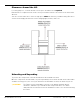
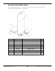
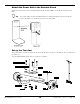
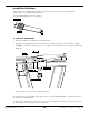
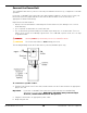
Table Of Contents
- MD-6XP Mid Rise Lift
- Table of Contents
- Introduction
- Shipping Information
- Safety Considerations
- Components
- Specifications
- Installation Checklist
- Installation
- Safety Rules
- Tools
- Select a Site
- Planning for Electrical Work (220 VAC only)
- Clearance Around the Lift
- Unloading and Unpacking
- Assemble the Portable Stand
- Attach the Power Unit to the Portable Stand
- Set up the Tow Cart
- Hydraulic Fluid Contamination
- About Thread Sealants
- Connect the Hydraulic Hoses
- Install the Lift Arms
- Connect the Power Unit
- Install a Thermal Disconnect Switch
- Fill the Hydraulic Fluid Reservoir
- Test the Lift
- Final Checklist Before Operation
- Operation
- Maintenance
- Troubleshooting
- Wiring Diagrams
- Labels
- Parts Diagrams
- Maintenance Log
- Maintenance Log
- Automotive Lift Institute (ALI) Store

MD-6XP Mid-Rise Scissor Lift 18 P/N 5900108 — Rev. F2 — April 2021
Install the Lift Arms
The Lift Arms are used with the Lift Pad accessories so that you can raise a Vehicle by the
manufacturer’s recommended Lifting Points.
The following drawing shows the Lift Arm.
To install the Lifting Arms:
1. Remove the Washer and Nut from the Lift Arm Pin.
2. Slide the Pin through the Channel and secure the Pin in place with the same Washer and Nut.
Do
not
over-tighten the Nut; keep it loose enough so that the Arm can move and pivot within the
Channel.
3. Repeat Steps 1 and 2 for the remaining Lift Arms.
Each Lift Arm can be fitted with either a Short Pad or a Tall Pad/Adapter/Base combination based on
the Vehicles you will be raising.
To switch them, remove the Lock Screw on the end of the Lift Arm, remove the current Pad, slide on
the desired Pad, and then replace the Lock Screw.