
Full Product Manual
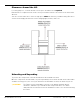
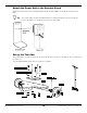
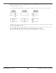
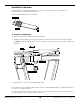
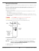
Table Of Contents
- MD-6XP Mid Rise Lift
- Table of Contents
- Introduction
- Shipping Information
- Safety Considerations
- Components
- Specifications
- Installation Checklist
- Installation
- Safety Rules
- Tools
- Select a Site
- Planning for Electrical Work (220 VAC only)
- Clearance Around the Lift
- Unloading and Unpacking
- Assemble the Portable Stand
- Attach the Power Unit to the Portable Stand
- Set up the Tow Cart
- Hydraulic Fluid Contamination
- About Thread Sealants
- Connect the Hydraulic Hoses
- Install the Lift Arms
- Connect the Power Unit
- Install a Thermal Disconnect Switch
- Fill the Hydraulic Fluid Reservoir
- Test the Lift
- Final Checklist Before Operation
- Operation
- Maintenance
- Troubleshooting
- Wiring Diagrams
- Labels
- Parts Diagrams
- Maintenance Log
- Maintenance Log
- Automotive Lift Institute (ALI) Store

MD-6XP Mid-Rise Scissor Lift 17 P/N 5900108 — Rev. F2 — April 2021
7. On the Power Unit, remove the Shipping Plug from the Hydraulic Out Port you want to use; it does
not matter which one you use.
The following drawing shows the possible port configurations, depending on your Power Unit.
Hydraulic Out Ports are usually labeled P on the Power Unit. Not all components of the Power Unit
are shown. Not drawn to scale.
8. Attach the ORB end of the Male Quick-Connect Fitting to the Power Unit, then connect the other
end of the Male Quick-Connect Fitting to the Female Quick-Connect Fitting.
Once all Hoses and Fittings have been attached, securely tighten all connections.