645 Lemonwood Dr. Santa Paula, CA, 93060 USA Toll Free: (800) 253-2363 Telephone: (805) 933-9970 bendpak.com Portable Mid-Rise Scissor Lift Installation and Operation Manual Manual P/N 5900108 — Manual Revision F2 — April 2021 Models: • MD-6XP Designed and engineered by BendPak Inc. in Southern California, USA. Made in China. ⚠ DANGER Read the entire contents of this manual before using this product.
Manual. MD-6XP Mid-Rise Scissor Lift, Installation and Operation Manual, Manual Part Number 5900108, Manual Revision F2, Released April 2021. Copyright. Copyright © 2021 by BendPak Inc. All rights reserved. You may make copies of this document if you agree that: you will give full attribution to BendPak Inc., you will not make changes to the content, you do not gain any rights to this content, and you will not use the copies for commercial purposes. Trademarks.
Table of Contents Introduction 3 Operation 22 Shipping Information 4 Maintenance 27 Safety Considerations 4 Troubleshooting 28 Components 6 Wiring Diagrams 29 Specifications 7 Labels 30 Installation Checklist 8 Parts Diagrams 32 Installation 9 ALI Store 39 Introduction This manual describes the MD-6XP, which is a mid-rise, frame-engaging, scissor Lift that is portable and comes with a small footprint designed for narrower bays and low-ceiling garages.
Shipping Information Your equipment was carefully checked before shipping. Nevertheless, you should thoroughly inspect the shipment before you sign to acknowledge that you received it. When you sign the bill of lading, it tells the carrier that the items on the invoice were received in good condition. Do not sign the bill of lading until after you have inspected the shipment.
Symbols Following are the symbols used in this manual: ⚠ DANGER ⚠ WARNING ⚠ CAUTION NOTICE Tip Calls attention to an immediate hazard that will result in injury or death. Calls attention to a hazard or unsafe practice that could result in injury or death. Calls attention to a hazard or unsafe practice that could result in minor personal injury, product, or property damage. Calls attention to a situation that, if not avoided, could result in product or property damage.
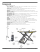
Components MD-6XP components include: • • • • • • • • • • • • • Scissor Structure. Holds the Lift together. Pivots in the middle. The two scissor pieces move together to raise the Lift, move apart to lower it. Power Unit. Provides Hydraulic Fluid to the Hydraulic Cylinders, which they use to raise the Scissor Structure. Connects to an external power source. Platform. Located on the top of the Scissor Structure. Holds the Arms and the Lift Pads. Hydraulic Cylinders.
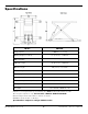
Specifications Model MD-6XP Lifting capacity 6,000 lbs. / 2,722 kg a Lifting Height (no Pads)* 47" (3.9 feet) / 1,190 mm b Overall Width 41.5" (3.6 feet) / 1,054 mm c Overall Length 76" (6.4 feet) / 1,930 mm d Frame Length 60" (5 feet) / 1,524 mm Lowered Height 4.75" / 121 mm Top Locking Position (no Pads)** 42" (3.5 feet) / 1,067 mm Middle Locking Position (no Pads)** 33.25" (2.8 feet) / 844 mm Bottom Locking Position (no Pads)** 22" (1.
Installation Checklist Following are the steps needed to install an MD-6XP Lift. Perform them in the order shown. ☐ 1. Review the installation Safety Rules. ☐ 2. Make sure you have the necessary Tools. ☐ 3. Select the Installation Site. ☐ 4. Planning for Electrical Work. ☐ 5. Check clearances. ☐ 6. Unloading and unpacking. ☐ 7. Assemble the Portable Stand. ☐ 8. Attach the Power Unit to the Portable Stand. ☐ 9. Set up the Tow Cart. ☐ 10. About Hydraulic Fluid Contamination. ☐ 11.
Installation This section describes how to install an MD-6XP. Perform the steps in the order listed. ⚠ WARNING Use only the factory-supplied parts that came with your Lift. If you use parts from a different source, you void your warranty and compromise the safety of everyone who installs or uses the Lift. If you are missing parts, visit bendpak.com/support or call (800) 253-2363, extension 191. Safety Rules When installing the Lift, your safety depends on proper training and thoughtful operation.
Select a Site The MD-6XP is portable, so you may be moving it and using it at a variety of locations. Keep the following in mind when selecting a location for your Lift: • • • • • • • • Clearance. You must have adequate space on all sides, plus enough space above for the Vehicles you will be raising. See Clearance Around the Lift for more information. Check for overhead obstructions.
Clearance Around the Lift For safety purposes, a certain amount of clear space around the Lift is required. Extra distance is required on both ends so that you can drive Vehicles onto and off of the Lift in either direction. You also need to make sure to leave enough space above the Vehicles you will be raising. Be sure to check for low-hanging obstructions such as hanging lights, beams, and so on. Unloading and Unpacking Try to have the components of the Lift unloaded near the installation location.
Assemble the Portable Stand The Portable Stand allows you to easily move the Power Unit to a location near the Lift. Assemble the Portable Stand as shown below. Item No. Part Number Description Qty 1 5601407 Low Rise Power Unit Stand 1 2 5737141 Low Rise Power Unit Extension Plate 1 3 5716192 Polyurethane Wheel 2 4 5545026 Washer M6 x Ø12 SL 2 5 5530027 HHB M6 x 1.0 x 35 2 6 5535357 Nut M6 x 1.0 NL 2 7 5545202 Washer M8 x Ø 15 SL 2 8 5530304 HHB M8 x 1.
Attach the Power Unit to the Portable Stand Attach the Power Unit to the Portable Stand using the included M8 x 25 mm Bolts, Washers, and Nuts. Tip The Power Unit is heavy and awkward. We recommend having one person hold the Power Unit while a second person bolts it onto the Stand. Set up the Tow Cart The Tow Cart lets you move the Lift around your work space. Keep the Tow Cart in an accessible area for future use. The following drawing shows how to set up the Tow Cart.
IMPORTANT! PLEASE READ NOW Hydraulic Fluid Contamination Hydraulic Fluid Contamination poses a serious issue for your Lift; contaminants such as water, dirt, or other debris can get into the Hydraulic Hoses and Fittings on the Lift, making your new Lift inoperable. Your Lift is shipped with clean components; however, Bendpak strongly recommends that you take secondary precaution and clean all Hydraulic Hoses and Fittings prior to making connections.
About Thread Sealants The efficiency of your Lift’s Hydraulic system relies on secure connections, which help prevent leaks and keep contaminants out. We recommend using a Liquid Thread Sealant (like Loctite™ 5452 or similar PTFE Thread Sealant) to seal the Hydraulic components on your Lift. Thread Sealant can be used with most Hydraulic Fittings, although you probably only need to use it with NPT connectors. To apply Thread Sealant: 1.
Connect the Hydraulic Hoses Hydraulic Hoses provide Hydraulic Fluid to the Hydraulic Cylinders, where it is used to raise the Platform. The Power Unit can be placed on either side of the Frame, as long as the operator has an unobstructed view of the Lift at all times. The following drawing shows how to route the Hydraulic Hoses on the Lift. Drawing shows Power Unit on the left side of the Frame. Drawing not to scale. Some components not shown, other components exaggerated for clarity.
7. On the Power Unit, remove the Shipping Plug from the Hydraulic Out Port you want to use; it does not matter which one you use. The following drawing shows the possible port configurations, depending on your Power Unit. Hydraulic Out Ports are usually labeled P on the Power Unit. Not all components of the Power Unit are shown. Not drawn to scale. 8.
Install the Lift Arms The Lift Arms are used with the Lift Pad accessories so that you can raise a Vehicle by the manufacturer’s recommended Lifting Points. The following drawing shows the Lift Arm. To install the Lifting Arms: 1. Remove the Washer and Nut from the Lift Arm Pin. 2. Slide the Pin through the Channel and secure the Pin in place with the same Washer and Nut. Do not over-tighten the Nut; keep it loose enough so that the Arm can move and pivot within the Channel. 3.
Connect the Power Unit The standard Power Unit for your Lift comes fully assembled from the factory, configured for 115 VAC operation. If you have a 220 VAC Power Unit, it will come with a pigtail for wiring to a power source. Have your Electrician remove the pigtail and wire from inside the Electrical Box on the Power Unit to an appropriate Power Cord and Plug.
Install a Thermal Disconnect Switch ⚠ WARNING The motor on the Power Unit supplied with your Lift has no thermal overload protection. Have the Electrician connect a motor Thermal Disconnect Switch or overload device that will make sure the equipment shuts down in the event of an overload or an overheated motor. ⚠ DANGER Installing a Thermal Disconnect Switch must be performed by a licensed, certified Electrician.
Test the Lift Before putting your Lift into normal operation, we recommend raising and lowering it a few times. This will help you get a feel for how to operate the controls and help get any residual air out of the Hydraulic System (sometimes called “bleeding” the system). Tip Residual air in the Hydraulic System can cause the Lift to shake, move erratically, or squeak; this is normal when you first start using the Lift. It will soon stop doing this, as the Hydraulic System is self-bleeding.
Operation This section describes how to operate your Automotive Lift. ⚠ DANGER When you even hear the words “Automotive Lift,” your brain should automatically remember that lifting a Vehicle is a serious endeavor with life-threatening risks. Focus on what you are doing. Automotive Lifts are dangerous tools when used by inexperienced or impaired operators. Do not assume you are going to be safe this time because nothing happened last time.
⚠ WARNING Always position the Lift Arms and Pads under the Vehicle so that they are directly under the manufacturers lifting points. If you are unsure of the Lifting Points’ location, consult Vehicle Lifting Points for Frame Engaging Lifts, which is available on the ALI website. (www.autolift.org/ali-store) Keep loads centered and balanced. Each time before you raise a Vehicle on your Lift: • • • Check the Lift. Walk all the way around the Lift, checking for any missing, heavily worn, or damaged parts.
• • • not allow anyone under the influence of drugs, alcohol, or medication to operate the Lift. Do not allow any unauthorized personnel to operate the Lift. Check for safety. Make sure everyone who is going to be walking near the Lift is aware of its presence and takes appropriate safety measures. Only put Vehicles on the Platform. When raising a Vehicle, do not leave it until it is engaged on a Safety Lock. When lowering the Lift, do not leave it until it is on the ground. Check the Vehicle.
If you miss the desired Safety Lock, there’s no problem; just try it again until you get it right. Raising a Vehicle This section describes how to raise a Vehicle on the Lift. To raise a Vehicle: 1. Check the items listed in Safety Considerations. If you find any issues, resolve them before raising the Vehicle; only use the Lift if it can be used safely. 2. Make sure the Lift is fully lowered and the Lift Arms are out of the way. 3. Drive the Vehicle over the Lift and then stop. 4.
If the Lift becomes unstable or the Vehicle starts moving, release the Up Button immediately. 11. Check to make sure the Lift Arms are making solid contact with the Lifting Points. If any of the Lift Pads are not making solid contact with the Lifting Points, lower the Lift and adjust the Lift Pads so that they make better contact. 12. Rock the Vehicle to make sure the Vehicle is stable and balanced. If the Vehicle is not stable and balanced, lower the Lift back to the ground and start over.
3. Press and hold the Lowering Handle on the Power Unit. 4. When the Lift is fully lowered, release the Lowering Handle. 5. Push the Lift Arms in towards the Frame. This is so they are not in the way when the Vehicle is moved. 6. Carefully drive the Vehicle off the Lift. Move the Lift ⚠ DANGER Do not move the Lift or perform any maintenance without first confirming that electrical power has been disconnected and cannot be re-energized. The following drawing shows the components used to move the Lift.
Maintenance ⚠ DANGER Before performing maintenance on your Lift, make sure it is disconnected from power. The Lift uses electrical energy; if your organization has Lockout/Tagout policies, make sure to implement them before performing any maintenance. If you come into contact with high voltage/current, you could be injured or killed. To maintain your Lift: • • • • • • • Daily: Keep the Lift clean. Wipe up any oil spills, clean any dirt.
Troubleshooting This section describes how to troubleshoot your Lift. Note: If your Lift is not functioning correctly, you must take it out of service until it is fixed. All repair work must be done by qualified personnel. ⚠ WARNING The Lift uses electrical energy; if your organization has Lockout/Tagout policies, make sure to implement them before performing any Troubleshooting. Issue Action to Take Platform moves erratically or squeaks when in use.
Wiring Diagrams 5585435 MD-6XP Mid-Rise Scissor Lift 30 P/N 5900108 — Rev.
Labels MD-6XP Mid-Rise Scissor Lift 31 P/N 5900108 — Rev.
MD-6XP Mid-Rise Scissor Lift 32 P/N 5900108 — Rev.
Parts Diagrams MD-6XP Mid-Rise Scissor Lift 33 P/N 5900108 — Rev.
MD-6XP Mid-Rise Scissor Lift 34 P/N 5900108 — Rev.
MD-6XP Mid-Rise Scissor Lift 35 P/N 5900108 — Rev.
MD-6XP Mid-Rise Scissor Lift 36 P/N 5900108 — Rev.
Maintenance Log MD-6XP Mid-Rise Scissor Lift 37 P/N 5900108 — Rev.
Maintenance Log MD-6XP Mid-Rise Scissor Lift 38 P/N 5900108 — Rev.
Automotive Lift Institute (ALI) Store You probably checked the ALI’s Directory of Certified Lifts (www.autolift.org/ali-directory-ofcertified-lifts/) before making your most recent Lift purchase, but did you know the ALI Store (www.autolift.
1645 Lemonwood Drive Santa Paula, CA 93060 USA © 2021 by BendPak Inc. All rights reserved. bendpak.