
Product Brochure
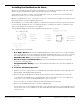
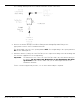
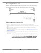
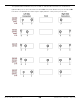
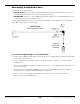
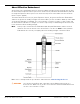
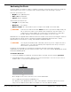
Table Of Contents
- HD-7P and HD-7W Manual
- Table of Contents
- Introduction
- Shipping Information
- Safety Considerations
- Components
- Specifications
- Frequently Asked Questions
- Installation Checklist
- Installation
- Being Safe
- Tools
- Planning for Electrical Work
- Selecting an Approach Direction
- Selecting a Power Post Location
- Checking Clearances
- Selecting a Location
- Unloading and Unpacking
- Creating Chalk Line Guides
- Moving the Posts into Position
- Installing the Crosstubes
- About Safety Locks
- Installing the Ladders and Top Cap
- Raising the Crosstubes
- Securing the Ladders
- Removing Sheaves
- Installing the Runways
- Installing the First End of the Flex Tube
- Routing the Lifting Cables
- Working with Compression Fittings and Tubing
- Installing the Air Lines
- Installing the Hydraulic Hose
- Installing the Return Line
- Installing the Power Unit
- Filling the Hydraulic Fluid Reservoir
- Installing the Second End of the Flex Tube
- Installing the Pushbutton Air Valve
- Connecting the Return Line
- Connecting the Hydraulic Hose
- Contacting the Electrician
- Connecting to a Power Source
- Installing a Power Disconnect Switch
- Installing a Thermal Disconnect Switch
- About Effective Embedment
- Anchoring the Posts
- Final Leveling
- Installing Accessories
- Lubricating the Lift
- Performing an Operational Test
- Reviewing the Final Checklist
- Operation
- Maintenance
- Troubleshooting
- Wiring Diagrams
- Labels
- Parts Drawings
- Automotive Lift Institute (ALI) Store
- Maintenance Log

HD-7P / HD-7W Four-Post Lifts 57 P/N 5900041 — Rev. M — July 2019
Connecting to a Power Source
The Power Unit must be connected to an appropriate power source.
⚠ DANGER All wiring
must
be performed by a licensed, certified Electrician. Do not perform
any maintenance or installation on the Lift without first making sure that main
electrical power has been disconnected from the Lift and cannot be re-energized
until all procedures are complete. The Lift uses electrical energy; if your organization
has Lockout/Tagout policies, make sure to implement them after connecting to a
power source.
Important: Make clear to your Electrician that all electrical work
must
conform to applicable local,
state, and federal codes, rules, and regulations, such as state and federal OSHA
regulations and electrical codes.
Your Lift was ordered with one of the following Power Units:
• 220 VAC, 60 Hz, 1 Phase. 220 VAC, for North American countries (U.S., Mexico, Canada).
Could be Power Unit 5585280 or 5585181.
• 110 VAC. 110 VAC, for North American countries (U.S., Mexico, Canada). Should be Power Unit
5585178.
• 220 VAC, 50/60 Hz, 1 Phase. 220 VAC, for countries outside North America. Could be Power
Unit 5585182 or 5585247.
Power Units are provided by different vendors so there may be minor differences in look and feel.
However, all Power Units of the same type provide the same level of functionality.
All Power Units come with a ‘pigtail’ coming out of the Electrical Box. To connect your Power Unit to a
power source, remove the pigtail and connect the Electrical Box to the electrical system at your
location or to an appropriate power cord with plug.
Make clear to your Electrician that all electrical work
must
conform to applicable local, state and
federal codes, rules, and regulations, such as state and federal OSHA regulations and electrical codes.
⚠ DANGER The following procedure
must
only be performed by a licensed, certified
Electrician.
To connect the Lift to a power source:
1. Locate the Pigtail coming out of the Electrical Box on the Power Unit.
2. Open the Electrical Box,
remove the Pigtail
, and then either:
– Wire the Power Unit directly into the facility’s electrical system.
– Wire a power cord with appropriate plug inside the Electrical box where the Pigtail was wired.
Wiring information is either on the outside of the Power Unit under the Electrical Box or inside the
cover of the Electrical Box. Have the Electrician use that wiring information to wire the Power Unit
to the power source.
You can also find the Wiring Diagram for your Power Unit in Wiring Diagrams.
3. Close the Electrical Box.