
Product Brochure
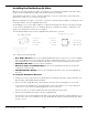
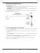
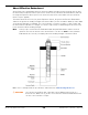
Table Of Contents
- HD-7P and HD-7W Manual
- Table of Contents
- Introduction
- Shipping Information
- Safety Considerations
- Components
- Specifications
- Frequently Asked Questions
- Installation Checklist
- Installation
- Being Safe
- Tools
- Planning for Electrical Work
- Selecting an Approach Direction
- Selecting a Power Post Location
- Checking Clearances
- Selecting a Location
- Unloading and Unpacking
- Creating Chalk Line Guides
- Moving the Posts into Position
- Installing the Crosstubes
- About Safety Locks
- Installing the Ladders and Top Cap
- Raising the Crosstubes
- Securing the Ladders
- Removing Sheaves
- Installing the Runways
- Installing the First End of the Flex Tube
- Routing the Lifting Cables
- Working with Compression Fittings and Tubing
- Installing the Air Lines
- Installing the Hydraulic Hose
- Installing the Return Line
- Installing the Power Unit
- Filling the Hydraulic Fluid Reservoir
- Installing the Second End of the Flex Tube
- Installing the Pushbutton Air Valve
- Connecting the Return Line
- Connecting the Hydraulic Hose
- Contacting the Electrician
- Connecting to a Power Source
- Installing a Power Disconnect Switch
- Installing a Thermal Disconnect Switch
- About Effective Embedment
- Anchoring the Posts
- Final Leveling
- Installing Accessories
- Lubricating the Lift
- Performing an Operational Test
- Reviewing the Final Checklist
- Operation
- Maintenance
- Troubleshooting
- Wiring Diagrams
- Labels
- Parts Drawings
- Automotive Lift Institute (ALI) Store
- Maintenance Log

HD-7P / HD-7W Four-Post Lifts 54 P/N 5900041 — Rev. M — July 2019
The Hydraulic Out and Return Line ports for HD-7P and HD-7W Power Units are shown below.
Hydraulic Out ports on the Power Units are labeled P below, while Return Line ports are labeled R.
Port labels on individual Power Units may be slightly different or may not be present at all.